Passive Piezo-Buzzer
KY-006 Controlled with PWM signals of different frequencies, the passive piezo buzzer can be used to generate different sounds.
- Arduino
- Raspberry Pi
- Raspberry Pi Pico
- Micro:Bit
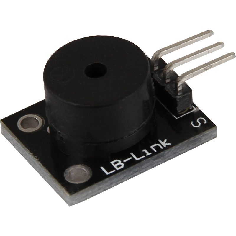
With this module, you can generate different sounds by controlling the passive piezo buzzer with PWM signals. PWM signals are special electrical signals that can be sent at different frequencies to generate different sounds. The buzzer can generate sounds in the range of 1.5 kHz to 2.5 kHz. It works with a voltage of 3.3 V to 5 V and is small and compact, with dimensions of 18.5 x 15 mm. This module is ideal if you need acoustic signals or alarm tones in your projects and is easy to integrate.
| Technical Data | |
|---|---|
| Operating voltage | 3,3 V - 5 V |
| Tone generation range | 1,5 kHz - 2,5 kHz |
| Dimensions | 18,5 x 15 mm |
Pin assignment


| Arduino | Sensor |
|---|---|
| Pin 8 | Signal |
| - | +V |
| GND | GND |
Code-Example
This is an example program which generates an alarm signal at the buzzer using a square wave voltage.
To load the following code example onto your Arduino, we recommend using the Arduino IDE. In the IDE, you can select the appropriate port and board for your device.
Copy the code below into your IDE. To upload the code to your Arduino, simply click on the upload button.
int buzzer = 8 ; // Declaration of the buzzer output pin

void setup() {
  pinMode(buzzer, OUTPUT); // Initialization as output pin
}
void loop() {
  unsigned char i;
  while(1) {
    // In this program, the buzzer is controlled alternately with two different frequencies
    // The signal here consists of a square wave voltage.
    // Turning the buzzer on and off then generates a tone that corresponds approximately to the frequency.
    // The frequency is defined by how long the on and off phases are

    // 1.frequency
    for(i = 0; i <80; i++) {
      digitalWrite(buzzer, HIGH);
      delay(1);
      digitalWrite(buzzer, LOW);
      delay(1);
    }

    // 1 second pause
    delay(1000);

    // 2.frequency
    for(i = 0; i <100; i++) {
      digitalWrite(buzzer, HIGH);
      delay(2) ;
      digitalWrite(buzzer, LOW);
      delay(2);
    }

    // 1 second pause
    delay(1000);
  }
}
With this module, you can generate different sounds by controlling the passive piezo buzzer with PWM signals. PWM signals are special electrical signals that can be sent at different frequencies to generate different sounds. The buzzer can generate sounds in the range from 1.5 kHz to 2.5 kHz. It works with a voltage of 3.3 V to 5 V and is small and compact, with dimensions of 18.5 x 15 mm. This module is ideal if you need acoustic signals or alarm tones in your projects and is easy to integrate.
| Technical Data | |
|---|---|
| Operating voltage | 3,3 V - 5 V |
| Tone generation range | 1,5 kHz - 2,5 kHz |
| Dimensions | 18,5 x 15 mm |
Pin assignment

| Raspberry Pi | Sensor |
|---|---|
| GPIO 24 [Pin 18] | Signal |
| 3.3 V [Pin 1] * | +V * |
| GND [Pin 6] | GND |
To prevent the supply voltage from dropping, the sensor on the Raspberry Pi must also be connected to +3.3V, since the supply via the signal pin may not be sufficient.
Code-Example
The example program uses software PWM to create a square wave voltage with definable frequency at the output pin.
By switching on and off, a tone is generated at the buzzer that corresponds approximately to the frequency of the square wave voltage.
from gpiozero import PWMOutputDevice

# The output pin to which the buzzer is connected is declared here.
buzzer = PWMOutputDevice(24, frequency=500, initial_value=0.5)

# The program waits for the user to enter a new PWM frequency.
# Until then, the buzzer is operated at the previously entered frequency (starting value 500Hz)
try:
    while True:
        print("----------------------------------------")
        aktuelle_frequenz = buzzer.frequency
        print(f"Current frequency: {aktuelle_frequenz:.0f}")
        neue_frequenz = int(input("Please enter a new frequency (50-5000): "))
        buzzer.frequency = neue_frequenz

# Clean-up work after the program has been completed
except KeyboardInterrupt:
    buzzer.close()
    print("Program ended")
With this module, you can generate different sounds by controlling the passive piezo buzzer with PWM signals. PWM signals are special electrical signals that can be sent at different frequencies to generate different sounds. The buzzer can generate sounds in the range from 1.5 kHz to 2.5 kHz. It works with a voltage of 3.3 V to 5 V and is small and compact, with dimensions of 18.5 x 15 mm. This module is ideal if you need acoustic signals or alarm tones in your projects and is easy to integrate.
| Technical Data | |
|---|---|
| Operating voltage | 3,3 V - 5 V |
| Tone generation range | 1,5 kHz - 2,5 kHz |
| Dimensions | 18,5 x 15 mm |
Pin assignment

| Micro:Bit | Sensor |
|---|---|
| Pin 0 | Signal |
| 3 V | +V |
| GND | GND |
Since this sensor is controlled by PWM it has to be connected to pin 0 of the Micro:Bit since that is the PWM pin of the Micro:Bit.
Code-Example
		input.onButtonPressed(Button.A, function () {
		    music.playMelody("C F D G E A F B ", 500)
		})
Sample program download
With this module, you can generate different sounds by controlling the passive piezo buzzer with PWM signals. PWM signals are special electrical signals that can be sent at different frequencies to generate different sounds. The buzzer can generate sounds in the range from 1.5 kHz to 2.5 kHz. It works with a voltage of 3.3 V to 5 V and is small and compact, with dimensions of 18.5 x 15 mm. This module is ideal if you need acoustic signals or alarm tones in your projects and is easy to integrate.
| Technical Data | |
|---|---|
| Operating voltage | 3,3 V - 5 V |
| Tone generation range | 1,5 kHz - 2,5 kHz |
| Dimensions | 18,5 x 15 mm |
Pin assignment

| Raspberry Pi Pico | Sensor |
|---|---|
| GPIO15 | Signal |
| - | +V |
| GND | GND |
Code-Example
This is a sample program that plays a song at the buzzer.
To load the following code example onto your Pico, we recommend using the Thonny IDE. All you have to do first is go to Run > Configure interpreter ... > Interpreter > Which kind of interpreter should Thonny use for running your code? and select MicroPython (Raspberry Pi Pico).
Now copy the code below into your IDE and click on Run.
# Load libraries
from machine import Pin, PWM
from utime import sleep

# Initialization of GPIO15 as PWM pin
buzzer = PWM(Pin(15))

# Defining the different pitches
tones = {
"B0": 31,
"C1": 33,
"CS1": 35,
"D1": 37,
"DS1": 39,
"E1": 41,
"F1": 44,
"FS1": 46,
"G1": 49,
"GS1": 52,
"A1": 55,
"AS1": 58,
"B1": 62,
"C2": 65,
"CS2": 69,
"D2": 73,
"DS2": 78,
"E2": 82,
"F2": 87,
"FS2": 93,
"G2": 98,
"GS2": 104,
"A2": 110,
"AS2": 117,
"B2": 123,
"C3": 131,
"CS3": 139,
"D3": 147,
"DS3": 156,
"E3": 165,
"F3": 175,
"FS3": 185,
"G3": 196,
"GS3": 208,
"A3": 220,
"AS3": 233,
"B3": 247,
"C4": 262,
"CS4": 277,
"D4": 294,
"DS4": 311,
"E4": 330,
"F4": 349,
"FS4": 370,
"G4": 392,
"GS4": 415,
"A4": 440,
"AS4": 466,
"B4": 494,
"C5": 523,
"CS5": 554,
"D5": 587,
"DS5": 622,
"E5": 659,
"F5": 698,
"FS5": 740,
"G5": 784,
"GS5": 831,
"A5": 880,
"AS5": 932,
"B5": 988,
"C6": 1047,
"CS6": 1109,
"D6": 1175,
"DS6": 1245,
"E6": 1319,
"F6": 1397,
"FS6": 1480,
"G6": 1568,
"GS6": 1661,
"A6": 1760,
"AS6": 1865,
"B6": 1976,
"C7": 2093,
"CS7": 2217,
"D7": 2349,
"DS7": 2489,
"E7": 2637,
"F7": 2794,
"FS7": 2960,
"G7": 3136,
"GS7": 3322,
"A7": 3520,
"AS7": 3729,
"B7": 3951,
"C8": 4186,
"CS8": 4435,
"D8": 4699,
"DS8": 4978
}

# Defining the song to be played in a list
song = ["E5","G5","A5","P","E5","G5","B5","A5","P","E5","G5","A5","P","G5","E5"]

# Function for setting the output frequency
def playtone(frequency):
    buzzer.duty_u16(1000)
    buzzer.freq(frequency)

# Function for switching off the buzzer
def bequiet():
    buzzer.duty_u16(0)

# Function for outputting the song to be played
def playsong(mysong):
    for i in range(len(mysong)):
        if (mysong[i] == "P"):
            bequiet()
        else:
            playtone(tones[mysong[i]])
        sleep(0.3)
    bequiet()

# Output of the defined song
playsong(song)