KY-019 5V Relais
This module is a 5V relay for switching higher currents.
- Arduino
- Raspberry Pi
- Raspberry Pi Pico
- Micro:Bit
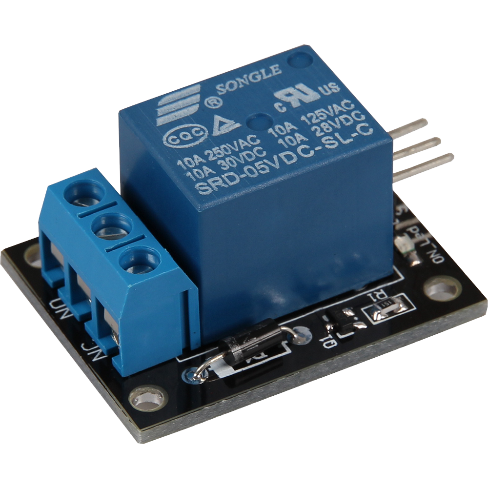
This module contains a 5V relay that is used for switching higher currents. The relay switches the applied voltage through as soon as 5V is applied to the voltage input of the switch. This allows it to be controlled in order to safely switch larger electrical loads on and off.
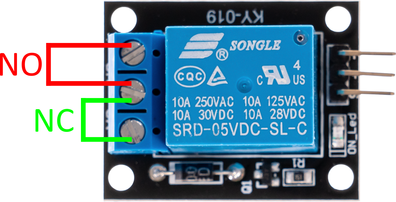
The relay module has two output terminals:
NC (normally closed): This output is closed by default without electrical switching. This means that the current flows through this path as long as the relay is not activated. NO (normally open): This output is open by default without electrical switching. This means that the current only flows through this path when the relay is activated. With these two output terminals, you can control whether the circuit should be closed or open in the idle state and change the current supply accordingly by applying 5V to the voltage input of the relay. This module is ideal for applications where it is necessary to safely switch higher loads or devices, such as in home automation systems, industrial control systems or other projects that require reliable power switching.
Working with voltages of more than 30 V and especially with mains voltage (230 V) can lead to physical injury and can even be fatal. We advise that work with higher voltages should only be carried out with the appropriate technical expertise.
| Technical Data | |
|---|---|
| Voltage range (AC) | 0 V - 240 V AC at 10 A |
| Voltage range (DC) | 0 V - 28 V DC at 10 A |
| Required switching current | ca. 15 - 20 mA |
| Relay type | Changeover switch |
| Dimensions | 53 x 18 x 20 mm |
Pin assignment


| Arduino | Sensor |
|---|---|
| Pin 10 | signal |
| 5 V | +V |
| GND | GND |
The program simulates a flashing light - it switches the relay between the two states (or output terminals) in predefined time (delayTime).
To load the following code example onto your Arduino, we recommend using the Arduino IDE. In the IDE, you can select the appropriate port and board for your device.
Copy the code below into your IDE. To upload the code to your Arduino, simply click on the upload button.
Code example
// The pin to which the relay is connected is declared here
int relay = 10;
// Value in seconds, how long to wait between switchovers
int delayTime = 1;

void setup () {
  pinMode(relay, OUTPUT); // The pin is declared as an output
}

// The program simulates a blinker - it switches the relay between the two states (or output terminals) in a predefined
// time (delayTime) between the two states (or output terminals).
void loop () {
  // “NO” is now short-circuited
  digitalWrite(relay, HIGH);
  delay(delayTime * 1000);
  // “NC” is now short-circuited
  digitalWrite(relay, LOW);
  delay(delayTime * 1000);
}
This module contains a 5V relay that is used for switching higher currents. The relay switches the applied voltage through as soon as 5V is applied to the voltage input of the switch. This allows it to be controlled in order to safely switch larger electrical loads on and off.
The relay module has two output terminals:
NC (normally closed): This output is closed by default without electrical switching. This means that the current flows through this path as long as the relay is not activated. NO (normally open): This output is open by default without electrical switching. This means that the current only flows through this path when the relay is activated. With these two output terminals, you can control whether the circuit should be closed or open in the idle state and change the current supply accordingly by applying 5V to the voltage input of the relay. This module is ideal for applications where it is necessary to safely switch higher loads or devices, such as in home automation systems, industrial control systems or other projects that require reliable power switching.
Working with voltages of more than 30 V and especially with mains voltage (230 V) can lead to physical injury and can even be fatal. We advise that work with higher voltages should only be carried out with the appropriate technical expertise.
| Technical Data | |
|---|---|
| Voltage range (AC) | 0 V - 240 V AC at 10 A |
| Voltage range (DC) | 0 V - 28 V DC at 10 A |
| Required switching current | ca. 15 - 20 mA |
| Relay type | Changeover switch |
| Dimensions | 53 x 18 x 20 mm |
Pin assignment

| Raspberry Pi | Sensor |
|---|---|
| GPIO 24 [Pin 18] | Signal |
| 5 V [Pin 2] | +V |
| GND [Pin 6] | GND |
Code example
The program simulates a flashing light - it switches the relay between the two states (or output terminals) in predefined time (delayTime).
# Required modules are imported and set up
import gpiozero
import time

# The relay control pin is declared here
RELAY_PIN = 24
relay = gpiozero.OutputDevice(RELAY_PIN, active_high=True, initial_value=False)

print("Sensor test [press CTRL+C to end the test]")

# Main program loop
try:
    while True:
        relay.on()
        print('Relay status: ' + str(relay.value))
        time.sleep(1)
        relay.off()
        print('Relay status: ' . str(relay.value))
        time.sleep(1)

# Clean-up work after the program has been completed
except KeyboardInterrupt:
    print("Test was terminated by the user")
    # gpiozero takes care of the cleanup when the script ends.
This module contains a 5V relay that is used for switching higher currents. The relay switches the applied voltage through as soon as 5V is applied to the voltage input of the switch. This allows it to be controlled in order to safely switch larger electrical loads on and off.
The relay module has two output terminals:
NC (normally closed): This output is closed by default without electrical switching. This means that the current flows through this path as long as the relay is not activated. NO (normally open): This output is open by default without electrical switching. This means that the current only flows through this path when the relay is activated. With these two output terminals, you can control whether the circuit should be closed or open in the idle state and change the current supply accordingly by applying 5V to the voltage input of the relay. This module is ideal for applications where it is necessary to safely switch higher loads or devices, such as in home automation systems, industrial control systems or other projects that require reliable power switching.
Working with voltages of more than 30 V and especially with mains voltage (230 V) can lead to physical injury and can even be fatal. We advise that work with higher voltages should only be carried out with the appropriate technical expertise.
| Technical Data | |
|---|---|
| Voltage range (AC) | 0 V - 240 V AC at 10 A |
| Voltage range (DC) | 0 V - 28 V DC at 10 A |
| Required switching current | ca. 15 - 20 mA |
| Relay type | Changeover switch |
| Dimensions | 53 x 18 x 20 mm |
Pin assignment

| Micro:Bit | Sensor |
|---|---|
| Pin 1 | Signal |
| 3 V | +V |
| GND | GND |
Code example
		input.onButtonPressed(Button.A, function () {
		    pins.digitalWritePin(DigitalPin.P1, 1)
		})
		input.onButtonPressed(Button.B, function () {
		    pins.digitalWritePin(DigitalPin.P1, 0)
		})
Sample program download
This module contains a 5V relay that is used for switching higher currents. The relay switches the applied voltage through as soon as 5V is applied to the voltage input of the switch. This allows it to be controlled in order to safely switch larger electrical loads on and off.
The relay module has two output terminals:
NC (normally closed): This output is closed by default without electrical switching. This means that the current flows through this path as long as the relay is not activated. NO (normally open): This output is open by default without electrical switching. This means that the current only flows through this path when the relay is activated. With these two output terminals, you can control whether the circuit should be closed or open in the idle state and change the current supply accordingly by applying 5V to the voltage input of the relay. This module is ideal for applications where it is necessary to safely switch higher loads or devices, such as in home automation systems, industrial control systems or other projects that require reliable power switching.
Working with voltages of more than 30 V and especially with mains voltage (230 V) can lead to physical injury and can even be fatal. We advise that work with higher voltages should only be carried out with the appropriate technical expertise.
| Technical Data | |
|---|---|
| Voltage range (AC) | 0 V - 240 V AC at 10 A |
| Voltage range (DC) | 0 V - 28 V DC at 10 A |
| Required switching current | ca. 15 - 20 mA |
| Relay type | Changeover switch |
| Dimensions | 53 x 18 x 20 mm |
Pin assignment

| Raspberry Pi Pico | Sensor |
|---|---|
| GPIO18 | Signal |
| External 5V | +V |
| GND + [External GND] | GND |
Code example
The program switches the relay between the two states (or output terminals) in predefined time.
To load the following code example onto your Pico, we recommend using the Thonny IDE. All you have to do first is go to Run > Configure interpreter ... > Interpreter > Which kind of interpreter should Thonny use for running your code? and select MicroPython (Raspberry Pi Pico).
Now copy the code below into your IDE and click on Run.
# Load libraries
from machine import Pin
from utime import sleep

# Initialization of GPIO18 as output
relay = Pin(18, Pin.OUT, value=0)

# Switch on relay
print("KY-019 Relay test")
print('NO short-circuited')
relay.on()

# wait 3 seconds
sleep(3)

# Switch off relay
print('NC short-circuited')
relay.off()