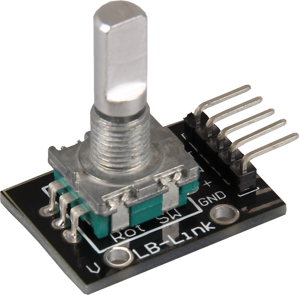
KY-040 Rotary encoder
When the rotary switch is moved, the direction of movement and the current position of the rotary switch are coded and output via the outputs.
- Arduino
- Raspberry Pi
- Raspberry Pi Pico
- Micro:Bit
The coded rotary switch (rotary encoder) outputs the direction of movement and the current position of the switch via its outputs when it is rotated.
The state of the two outputs changes with each step, allowing the direction of rotation to be determined. The direction of rotation is determined by the sequence of the state changes of the outputs: Depending on which output changes state first, it is possible to detect whether the switch is turned clockwise or counterclockwise.
This rotary switch is ideal for applications where precise position and movement information is required, such as in user interfaces for electronic devices, machine controls or in rotary measuring systems. It provides accurate and reliable input and is a versatile component for many projects.
Pin assignment


| Arduino | Sensor |
|---|---|
| 5 V | + V |
| GND | GND |
| Pin 3 | CLK |
| Pin 4 | DT |
| Pin 5 | SW |
Code example
The sample program checks for the change of the pin states and determines the direction of rotation as soon as a rotation has been detected. After the direction has been determined, the steps from the start position are counted and output. Pressing the button resets the count.
To load the following code example onto your Arduino, we recommend using the Arduino IDE. In the IDE, you can select the appropriate port and board for your device.
Copy the code below into your IDE. To upload the code to your Arduino, simply click on the upload button.
// Initialization of required variables
int counter = 0;
boolean direction;
int pin_clk_last;
int pin_clk_current;

// Definition of the input pins
int pin_clk = 3;
int pin_dt = 4;
int button_pin = 5;


void setup()  {
  // Input pins are initialized...
  pinMode(pin_clk,INPUT);
  pinMode(pin_dt,INPUT);
  pinMode(button_pin,INPUT);

  // ...and their pull-up resistors activated
  digitalWrite(pin_clk, true);
  digitalWrite(pin_dt, true);
  digitalWrite(button_pin, true);

  // Initial readout of the Pin_CLK
  pin_clk_last = digitalRead(pin_clk);
  Serial.begin (9600);
  Serial.println("KY-040 Rotary encoder test");
 }

// If a change in the pin states has occurred, the program checks which of the two pins changed first, indicating the direction of rotation.
// pins changed first, which indicates the direction of rotation.
// This information can be obtained by comparing one of the two pin values from a previous
// run with the value of the current run.
// Once the direction has been determined, the steps from the start position are counted and output.
// Pressing the rotary encoder button resets the current position.

void loop() {
  // Reading out the current status
  pin_clk_current = digitalRead(pin_clk);

  // Check for change
  if (pin_clk_current != pin_clk_last) {
    if (digitalRead(pin_dt) != pin_clk_current) {
      // Pin_CLK has changed first
      counter ++;
      direction = true;
    }
    else {
      // Otherwise Pin_DT has changed first
      direction = false;
      counter--;
    }
    delay(300);
    Serial.println("Rotation detected");
    Serial.print("Direction of rotation: ");
    if (direction) Serial.println ("Clockwise");
    else Serial.println("Counterclockwise");

    Serial.print("Current position: ");
    Serial.println(counter);
    Serial.println("------------------------------");
  }
  // Preparation for the next run:
  // The value of the current run is the previous value for the next run
  pin_clk_last = pin_clk_current;
  // Reset function to save current position
  if (!digitalRead(button_pin) && counter!=0) {
    counter = 0;
    Serial.println("Position reset");
  }
 }
The coded rotary switch (rotary encoder) outputs the direction of movement and the current position of the switch via its outputs when it is rotated.
The state of the two outputs changes with each step, allowing the direction of rotation to be determined. The direction of rotation is determined by the sequence of the state changes of the outputs: Depending on which output changes state first, it is possible to detect whether the switch is turned clockwise or counterclockwise.
This rotary switch is ideal for applications where precise position and movement information is required, such as in user interfaces for electronic devices, machine controls or in rotary measuring systems. It provides accurate and reliable input and is a versatile component for many projects.
Pin assignment

| Raspberry Pi | Sensor |
|---|---|
| GPIO 14 [pin 8] | Button |
| 3.3 V [pin 1] | + V |
| GND [pin 6] | GND |
| GPIO 16 [pin 36] | CLK |
| GPIO 15 [pin 10] | DT |
Code example
The sample program checks for the change of the pin states and determines the direction of rotation as soon as a rotation has been detected. After the direction has been determined, the steps from the start position are counted and output. Pressing the button resets the count.
import time
from gpiozero import Button

# Initialization of the pins for the rotary encoder
clk = Button(16, pull_up=True)
dt = Button(15, pull_up=True)
reset_button = Button(14, pull_up=True)  # Button for resetting the counter

last_clk_state = clk.is_pressed  # Saves the last status of CLK

# Initialize the counter
counter = 0

def read_encoder():
    global last_clk_state, counter
    while True:
        current_clk_state = clk.is_pressed
        if current_clk_state != last_clk_state:  # Recognize a change of state
            if current_clk_state:
                if dt.is_pressed != current_clk_state:
                    counter += 1  # Clockwise rotation
                    direction = "Clockwise"
                else:
                    counter -= 1  # Counterclockwise rotation
                    direction = "Counterclockwise"
                print(f"Direction of rotation: {direction}")
                print(f"Current position: {counter}")
                print("------------------------------")
            last_clk_state = current_clk_state
        time.sleep(0.001)  # short pause to save CPU time

def reset_counter():
    global counter
    counter = 0
    print("Counter reset!")
    print("------------------------------")

# Add an event handler for the reset button
reset_button.when_pressed = reset_counter

print("Sensor test [press CTRL+C to end the test]")

try:
    read_encoder()  # Start the function for reading the encoder
except KeyboardInterrupt:
    print("Program was interrupted by user")
The coded rotary switch (rotary encoder) outputs the direction of movement and the current position of the switch via its outputs when it is rotated.
The state of the two outputs changes with each step, allowing the direction of rotation to be determined. The direction of rotation is determined by the sequence of the state changes of the outputs: Depending on which output changes state first, it is possible to detect whether the switch is turned clockwise or counterclockwise.
This rotary switch is ideal for applications where precise position and movement information is required, such as in user interfaces for electronic devices, machine controls or in rotary measuring systems. It provides accurate and reliable input and is a versatile component for many projects.
Pin assignment

| Micro:Bit | Sensor |
|---|---|
| 3 V | +V |
| GND | GND |
| Pin 1 | CLK |
| Pin 2 | DT |
| Pin 0 | Button |
Code example
The sample program checks for the change of the pin states and determines the direction of rotation as soon as a rotation has been detected. After the direction has been determined, the steps from the start position are counted and output. Pressing the button resets the count.
		function RotaryEncoder () {
		    CLKAKTUELL = pins.digitalReadPin(DigitalPin.P1)
		    if (CLKAKTUELL != CLKLETZTE) {
		        if (pins.digitalReadPin(DigitalPin.P2) != CLKAKTUELL) {
		            Richtung = 1
		        } else {
		            Richtung = 0
		        }
		        serial.writeLine("Drehung Erkannt: ")
		        if (Richtung == 1) {
		            POS += -1
		            POSLETZTE = POS
		            serial.writeLine("Drehrichtung: Gegen den Uhrzeigersinn")
		        } else {
		            POS += 1
		            POSLETZTE = POS
		            serial.writeLine("Drehrichtung: Im Uhrzeigersinn")
		        }
		        serial.writeLine("Aktuelle Position: ")
		        serial.writeLine("" + (POS))
		    }
		    if (POS != VORHERIGEPOS) {
		        serial.writeLine("" + (POS))
		        VORHERIGEPOS = POS
		    }
		}
		pins.onPulsed(DigitalPin.P2, PulseValue.High, function () {
		    RotaryEncoder()
		})
		pins.onPulsed(DigitalPin.P2, PulseValue.Low, function () {
		    RotaryEncoder()
		})
		pins.onPulsed(DigitalPin.P0, PulseValue.Low, function () {
		    Reset()
		})
		function Reset () {
		    basic.pause(100)
		    CLKLETZTE = CLKAKTUELL
		    POS = 0
		}
		let VORHERIGEPOS = 0
		let POSLETZTE = 0
		let POS = 0
		let Richtung = 0
		let CLKAKTUELL = 0
		let CLKLETZTE = 0
		CLKLETZTE = 0
		CLKAKTUELL = 0
		Richtung = 1
		CLKLETZTE = pins.digitalReadPin(DigitalPin.P1)
		POS = 0
		POSLETZTE = 0
		pins.setPull(DigitalPin.P0, PinPullMode.PullUp)
		pins.setPull(DigitalPin.P1, PinPullMode.PullUp)
		pins.setPull(DigitalPin.P2, PinPullMode.PullUp)
Sample program download
The coded rotary switch (rotary encoder) outputs the direction of movement and the current position of the switch via its outputs when it is rotated.
The state of the two outputs changes with each step, allowing the direction of rotation to be determined. The direction of rotation is determined by the sequence of the state changes of the outputs: Depending on which output changes state first, it is possible to detect whether the switch is turned clockwise or counterclockwise.
This rotary switch is ideal for applications where precise position and movement information is required, such as in user interfaces for electronic devices, machine controls or in rotary measuring systems. It provides accurate and reliable input and is a versatile component for many projects.
Pin assignment

| Raspberry Pi Pico | Sensor |
|---|---|
| 5 V | +V |
| GND | GND |
| GPIO16 | CLK |
| GPIO17 | DT |
| GPIO18 | SW |
Code example
The sample program checks for the change of the pin states and determines the direction of rotation as soon as a rotation has been detected. After the direction has been determined, the steps from the start position are counted and output. Pressing the button resets the count.
To load the following code example onto your Pico, we recommend using the Thonny IDE. All you have to do first is go to Run > Configure interpreter ... > Interpreter > Which kind of interpreter should Thonny use for running your code? and select MicroPython (Raspberry Pi Pico).
Now copy the code below into your IDE and click on Run.
# Load libraries
from machine import Pin
from time import sleep

# Initialization of GPIO16, GPIO17 and GPIO18 as input
CLK = Pin(16,Pin.IN, Pin.PULL_DOWN)
DT = Pin(17,Pin.IN, Pin.PULL_DOWN)
SW = Pin(18,Pin.IN, Pin.PULL_UP)

# Variable definition
counter = 0
clk_last = CLK.value()
clk_current = 0
direction = True

print("KY-040 Rotary encoder test")
print("-------------------------------------------")

def output():
    global clk_current, counter, direction

    # Read out the current status
    clk_current = CLK.value()

    # Check for change
    if clk_current != clk_last:

        # Pin_CLK has changed first
        if DT.value() != clk_current:
            counter = counter + 1
            direction = True

        # Otherwise Pin_DT has changed first
        else:
            direction = False
            counter = counter - 1
        print("Rotation recognized: ")

        if direction:
            print("Direction of rotation: Clockwise")
        else:
            print("Direction of rotation: Counterclockwise")
        print("Current position: " + str(counter))
        print("-------------------------------------------")

# Function: Counter variable is reset when the button is pressed
def counterReset():
    global counter
    if SW.value() == 0:
        print("Position reset!")
        print("-----------------------")
        counter = 0
        sleep(0.5)

# Endless loop for constant reading of the sensor
while True:
    output()
    clk_last = clk_current
    counterReset()