KY-005 Infrared transmitter
A light emitting diode that emits in the infrared range.
- Arduino
- Raspberry Pi
- Raspberry Pi Pico
- Micro:Bit
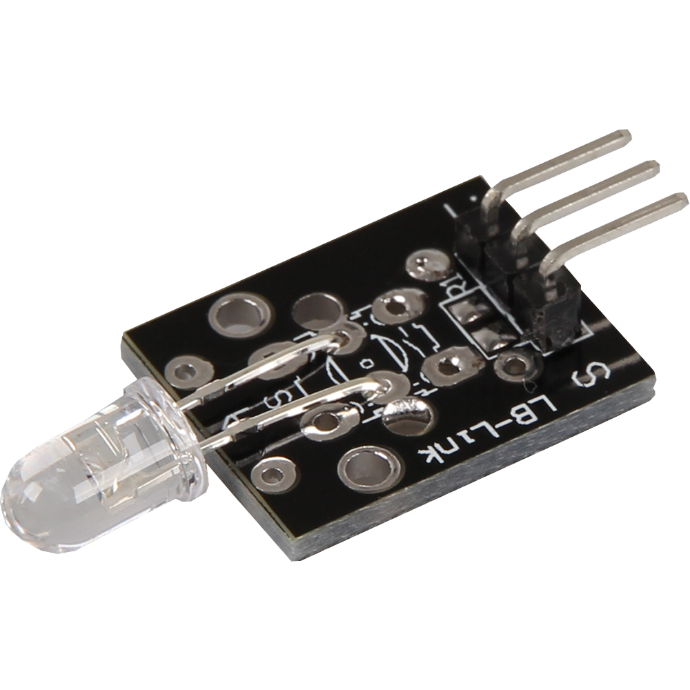
This module contains a light-emitting diode that emits infrared light. Infrared light is invisible to the human eye, but it is often used in many practical applications, such as remote controls or object recognition. The diode operates with a voltage of 1.1 V and a current of 20 mA. Depending on the input voltage, it is important to use series resistors to protect the LED and ensure smooth operation. These series resistors ensure that the correct amount of current flows through the diode, allowing it to be used effectively and safely. The module is ideal for projects that require infrared light and provides a reliable and simple solution for your infrared applications.
| Technical Data | |
|---|---|
| Forward voltage (Vf) | 1,1 V |
| Forward current (If) | 20 mA |
| Emitting wavelength | 940 nm (non-visible light |
Series resistors:
| Input voltage | Required series resistor |
|---|---|
| 3,3 V | 120 Ω |
| 5 V | 220 Ω |
Pin assignment

for more advanced users
On the PCB there is the possibility to directly solder the required resistor. The place for soldering the resistor is located directly above the connection pins on the PCB.

When soldering on the resistor, the pin assignment changes as follows:

| Arduino | Transmitter |
|---|---|
| Pin 3 | Signal |
| GND | GND+Resistor |
| - | GND |
for beginners

| Arduino | Transmitter |
|---|---|
| Pin 3 | Signal |
| - | GND+Resistor |
| GND+Resistor | GND |
Code-Example
With the help of the two sensor modules KY-005 and KY-022 a system with infrared remote control and infrared receiver can be built. For this purpose, two Arduinos are required in addition to the two modules. These then act as transmitters and receivers of the signals.
To load the following code example onto your Arduino, we recommend using the Arduino IDE. In the IDE, you can select the appropriate port and the correct board for your device. For the following code example an additional library is needed:
IRremote by Ken Shirriff | published under the MIT license.
You can easily add these libraries via the library manager of the Arduino IDE.
In infrared transmitting systems there are different protocols in which the data can be sent. In the following example, the NEC protocol is used for sending. Documentation.Please note: For the execution of the code example an additional file is necessary. This opens automatically as soon as you open the sample code from the IRremote library. Therefore, first open the example code via the following path: File > Examples > IRremote > SimpleSender.
Now you can replace the example code with our modified example. To upload the code to the Arduino, simply click on the upload button.
/*
 * SimpleSender.cpp
 *
 * Demonstrates the sending of IR codes in standard format with address and command
 * An extended example for sending can be found as SendDemo.
 *
 *  Copyright (C) 2020-2022  Armin Joachimsmeyer
 *  armin.joachimsmeyer@gmail.com
 *
 * This file is part of Arduino-IRremote https://github.com/Arduino-IRremote/Arduino-IRremote.
 *
 *  MIT License
 */
#include <Arduino.h>

#if !defined(ARDUINO_ESP32C3_DEV) // This is due to an error in the RISC-V compiler, which requires unused function sections :-(.
// Deactivates static receiver code such as the ISR handler for the receive timer and static IR receiver and irparams data.
// Saves 450 bytes of program memory and 269 bytes of RAM if the receive functions are not required.
#define DISABLE_CODE_FOR_RECEIVER
#endif

/*
 * This include defines the current pin numbers for pins such as IR_RECEIVE_PIN, IR_SEND_PIN for many different boards and architectures
 */
#include "PinDefinitionsAndMore.h"
#include <IRremote.hpp> // Including the library

void setup() {
    pinMode(LED_BUILTIN, OUTPUT);

    Serial.begin(115200);
    while (!Serial)
        ; // Wait for Serial to become available. Will be optimized away for some cores.

    // Just to know which program is running on my Arduino
    Serial.println(F("KY-005: Infrared transmitter test"));
    Serial.print(F("Send IR signals to pin "));
    Serial.println(IR_SEND_PIN);

    /*
     * Setting up the IR library. That's it already!
     */
    // Start with IR_SEND_PIN - which is defined in PinDefinitionsAndMore.h - as the send pin and activate the feedback LED on the standard feedback LED pin
    IrSender.begin();
    disableLEDFeedback(); // Deactivate feedback LED on the standard feedback LED pin
}

/*
 * Set up the data to be sent.
 * With most protocols, the data is sent with a constant 8- (or 16-byte) address
 * and a variable 8-bit command.
 * There are exceptions, such as Sony and Denon, which have a 5-bit address.
 */
uint8_t sCommand = 0x34;
uint8_t sRepeats = 0;

void loop() {
    /*
     * Display current transmission values
     */
    Serial.println();
    Serial.print(F("Now being sent: address=0x00, command=0x"));
    Serial.print(sCommand, HEX);
    Serial.print(F(", repeats="));
    Serial.print(sRepeats);
    Serial.println();

    Serial.println(F("Sending standard NEC with 8-bit address"));
    Serial.flush();

    // The receiver output for the first loop must be: Protocol=NEC Address=0x102 Command=0x34 Raw-Data=0xCB340102 (32 bits)
    IrSender.sendNEC(0x00, sCommand, sRepeats);

    /*
     * Increment send values
     */
    sCommand += 0x11;
    sRepeats++;
    // Clip repeats at 4
    if (sRepeats > 4) {
        sRepeats = 4;
    }

    delay(1000);  // Delay must be greater than 5 ms (RECORD_GAP_MICROS), otherwise the receiver sees it as a long signal
}
This module contains a light-emitting diode that emits infrared light. Infrared light is invisible to the human eye, but it is often used in many practical applications, such as remote controls or object recognition. The diode operates with a voltage of 1.1 V and a current of 20 mA. Depending on the input voltage, it is important to use series resistors to protect the LED and ensure smooth operation. These series resistors ensure that the correct amount of current flows through the diode, allowing it to be used effectively and safely. The module is ideal for projects that require infrared light and provides a reliable and simple solution for your infrared applications.
| Technical Data | |
|---|---|
| Forward voltage (Vf) | 1,1 V |
| Forward current (If) | 20 mA |
| Emitting wavelength | 940 nm (non-visible light |
Series resistors:
| Input voltage | Required series resistor |
|---|---|
| 3,3 V | 120 Ω |
| 5 V | 220 Ω |
On the PCB there is the possibility to directly solder the required resistor. The place for soldering the resistor is located directly above the connection pins on the PCB.
Pin assignment (ON-OFF example)

| Raspberry Pi | Sensor |
|---|---|
| GPIO 15 [Pin 10] | Signal |
| GND [Pin 6] | GND |
Code-Example (ON-OFF example)
# Required modules are imported
from gpiozero import LED
import time

# Initialize the LED on pin 15
led = LED(15)

print("LED test [press CTRL+C to end the test]")

# Main program loop
try:
    while True:
        print("LED on for 4 seconds")
        led.on()  # LED is switched on
        time.sleep(4)  # Wait mode for 4 seconds
        print("LED 2 Sekunden aus")
        led.off()  # LED is switched off
        time.sleep(2)  # Waiting mode for a further two seconds, during which the LED is then switched off

# Clean up after the program has been completed
except KeyboardInterrupt:
    led.close()  # Release of resources
Pin assignment (Remote control example)

| Raspberry Pi | Receiver |
|---|---|
| GPIO15 [Pin 10] | Signal |
| 3.3 V [Pin 1] | +V |
| GND [Pin 6] | GND |

| Raspberry Pi | Transmitter |
|---|---|
| GPIO14 [Pin 10] | Signal |
| GND [Pin 6] | GND |
Source of the now following steps.
First, open the config.txt file using the following command:
sudo nano /boot/config.txt
Now add the following content to the end of the file:
dtoverlay=gpio-ir,gpio_pin=15
dtoverlay=gpio-ir-tx,gpio_pin=14
With the key combination [CTRL+O] you can save the file. Confirm this with [Enter] and exit the editor with the key combination [CTRL+X]. Now restart your Raspberry Pi with the following command:
sudo reboot
Now install the ir-keytable module:
sudo apt-get install ir-keytable -y
With the following command you can determine the device identification. This is necessary to be able to address the receiver in the further course:
sudo ir-keytable
The first line of the output should look something like this:
Found /sys/class/rc/rc0/ (/dev/input/event0) with:
Here it can be read that we can address our receiver via the identification rc0. Therefore we start the reception now via the following command:
ir-keytable -t -s rc0
This module contains a light-emitting diode that emits infrared light. Infrared light is invisible to the human eye, but it is often used in many practical applications, such as remote controls or object recognition. The diode operates with a voltage of 1.1 V and a current of 20 mA. Depending on the input voltage, it is important to use series resistors to protect the LED and ensure smooth operation. These series resistors ensure that the correct amount of current flows through the diode, allowing it to be used effectively and safely. The module is ideal for projects that require infrared light and provides a reliable and simple solution for your infrared applications.
| Technical Data | |
|---|---|
| Forward voltage (Vf) | 1,1 V |
| Forward current (If) | 20 mA |
| Emitting wavelength | 940 nm (non-visible light |
Series resistors:
| Input voltage | Required series resistor |
|---|---|
| 3,3 V | 120 Ω |
| 5 V | 220 Ω |
On the PCB there is the possibility to directly solder the required resistor. The place for soldering the resistor is located directly above the connection pins on the PCB.
Pin assignment (ON-OFF Example)

| Micro:Bit | Transmitter |
|---|---|
| Pin 0 | Signal |
| - | +V |
| GND | GND |
Code-Example (ON-OFF Example)
Pin assignment (Remote control example)

| Micro:Bit | Transmitter |
|---|---|
| Pin 0 | Signal |
| - | +V |
| GND | GND |
| Micro:Bit | Receiver |
|---|---|
| Pin 1 | Signal |
| 3 V | +V |
| GND | GND |
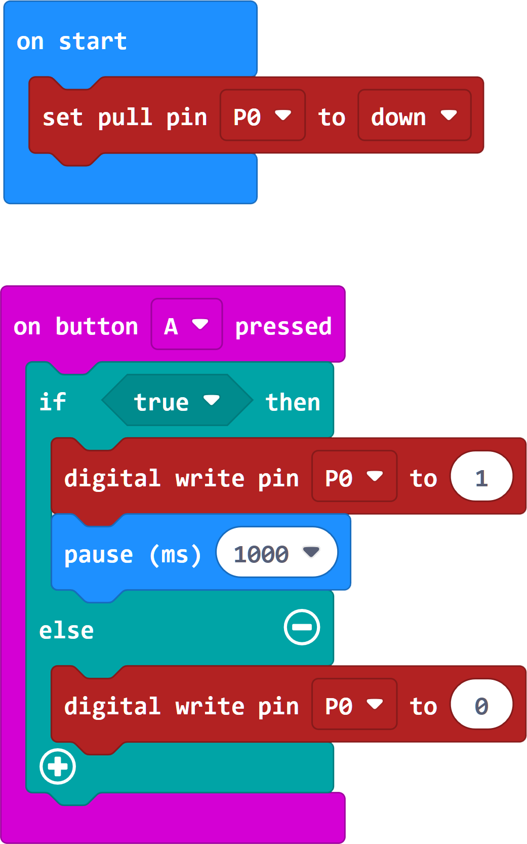
Code Example (Remote control example)
Two additional libraries are needed for the following code example:
pxt-makerbit-ir-transmitter from 1010Technologies | released under the MIT License
pxt-makerbit-ir-receiver by 1010Technologies | published under the MIT License.
You need to add these libraries to your IDE before using the code.
Add the library to your IDE by clicking on "Extensions" and entering each of the following URLs in the search box: https://github.com/1010Technologies/pxt-makerbit-ir-transmitter.git and https://github.com/1010Technologies/pxt-makerbit-ir-receiver.git Confirm the search in each case with Enter.
		makerbit.onIrDatagram(function () {
		    if (true) {
		        basic.showIcon(IconNames.SmallHeart)
		    } else {
		        basic.showIcon(IconNames.Heart)
		    }
		})
		makerbit.connectIrSenderLed(AnalogPin.P0)
		makerbit.connectIrReceiver(DigitalPin.P1, IrProtocol.NEC)
		basic.forever(function () {
		    makerbit.sendIrDatagram("0x00FF02FD")
		    basic.pause(500)
		})
Sample program download
This module contains a light-emitting diode that emits infrared light. Infrared light is invisible to the human eye, but it is often used in many practical applications, such as remote controls or object recognition. The diode operates with a voltage of 1.1 V and a current of 20 mA. Depending on the input voltage, it is important to use series resistors to protect the LED and ensure smooth operation. These series resistors ensure that the correct amount of current flows through the diode, allowing it to be used effectively and safely. The module is ideal for projects that require infrared light and provides a reliable and simple solution for your infrared applications.
| Technical Data | |
|---|---|
| Forward voltage (Vf) | 1,1 V |
| Forward current (If) | 20 mA |
| Emitting wavelength | 940 nm (non-visible light |
Series resistors:
| Input voltage | Required series resistor |
|---|---|
| 3,3 V | 120 Ω |
| 5 V | 220 Ω |
Pin assignment
for more advanced users
On the PCB there is the possibility to directly solder the required resistor. The place for soldering the resistor is located directly above the connection pins on the PCB.
When soldering on the resistor, the pin assignment changes as follows:

| Raspberry Pi Pico | Transmitter |
|---|---|
| GPIO17 | Signal |
| GND | GND+Resistor |
| - | GND |
for beginners

| Raspberry Pi Pico | Transmitter |
|---|---|
| GPIO17 | Signal |
| - | GND+Resistor |
| GND+Resistor | GND |
Code example
With the help of the two sensor modules KY-005 and KY-022 a system with infrared remote control and infrared receiver can be built. But here we will only use the transmitter with a pico. This then acts as a transmitter of the signals.
To load the following code example onto your Pico, we recommend using the Thonny IDE. All you have to do first is go to Run > Configure interpreter ... > Interpreter > Which kind of interpreter should Thonny use for running your code? and select MicroPython (Raspberry Pi Pico).
The following library is used for the code example:
micropython-ir by Peter Hinch | published under the MIT license.
To use this library, you must download the ir_tx folder from the above library and load it onto the Pico in a folder called lib (you may need to create this).
In infrared transmitting systems there are different protocols in which the data can be sent. In the following example, different protocols are used for sending. Documentation
Afterwards you can copy the code below into your IDE and click on Run.
# Load libraries
from machine import Pin
from ir_tx.nec import NEC
from time import sleep

# Initialization from transmitter with NEC protocol to GPIO26
nec = NEC(Pin(17, Pin.OUT, value = 0))

# Variables for sending the data
address = 0x00
data = 0x34

print("KY-005 Infrared transmitter test")

while True:
    # Display transmission values
    print("Now it will be sent: Address=", hex(address),", Command=", hex(data))
    # Send data
    nec.transmit(address, data)
    # Increment send values
    data += 0x11
    # wait one second
    sleep(1)