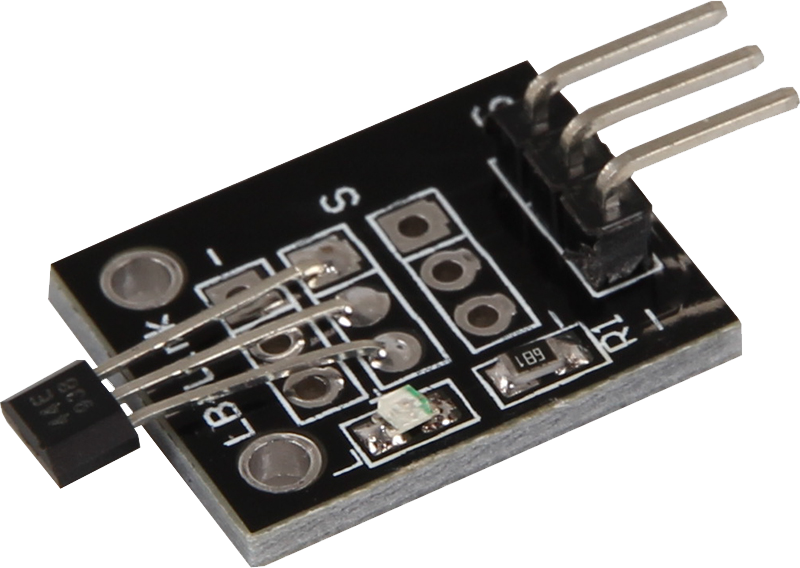
KY-003 Hall magnetic field sensor
Hall-effect switches are monolithic integrated circuits with tighter magnetic specifications, meaning that the sensor is made of one piece.
- Arduino
- Raspberry Pi
- Raspberry Pi Pico
- Micro:Bit

The Hall effect transistor/switch is an integrated circuit with specific magnetic properties that has all the necessary components already integrated into the sensor and offers increased sensitivity to magnetic fields. The module operates stably at temperatures up to +80 °C and is insensitive to temperature and supply voltage changes. Equipped with an A3144 chipset, each device includes a reverse polarity protection diode, a square Hall voltage generator, a temperature compensation circuit, a small signal amplifier, a Schmitt trigger and an open collector output.
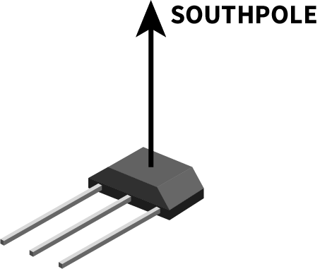
When the module is held in a magnetic field, the transistor switches through, which can be read out as a digital value at the signal output. This feature makes the Hall effect transistor/switch ideal for applications where the detection and measurement of magnetic fields is required, offering high reliability and precision.

| Technical Data | |
|---|---|
| Chipset | A3144 |
| Sensor type | Hall-effect transistors/switches |
| Operating voltage | 5V (Due to the LED) |
Pin Assignment
| Arduino | Sensor |
|---|---|
| Pin 10 | signal |
| 5 V | +V |
| GND | GND |
Code-Example
To load the following code example onto your Arduino, we recommend using the Arduino IDE. In the IDE, you can select the appropriate port and board for your device.
Copy the code below into your IDE. To upload the code to your Arduino, simply click on the upload button.
int hall = 10; // Declaration of the sensor input pin
int value; // Temporary variable

void setup () {
  pinMode(hall, INPUT); // Initialization sensor pin
  digitalWrite(hall, HIGH); // Activation of internal pull-up resistor
  Serial.begin(9600); // Initialization of the serial monitor
  Serial.println("KY-003 Magnetic detection");
}

void loop () {
  // The current signal from the sensor is read.
  value = digitalRead(hall);
  // If a signal could be detected, this is displayed on the serial monitor.
  if (value == LOW) {
    Serial.println("Signal detected");
    delay(100); // 100 ms break
    }
}

The Hall effect transistor/switch is an integrated circuit with specific magnetic properties that has all the necessary components already integrated in the sensor and offers increased sensitivity to magnetic fields. The module operates stably at temperatures up to +80 °C and is insensitive to temperature and supply voltage changes. Equipped with an A3144 chipset, each device includes a reverse polarity protection diode, a square Hall voltage generator, a temperature compensation circuit, a small signal amplifier, a Schmitt trigger and an open collector output.
When the module is held in a magnetic field, the transistor switches through, which can be read out as a digital value at the signal output. This feature makes the Hall effect transistor/switch ideal for applications where the detection and measurement of magnetic fields is required, offering high reliability and precision.

| Technical Data | |
|---|---|
| Chipset | A3144 |
| Sensor type | Hall-effect transistors/switches |
| Operating voltage | 5V (Due to the LED) |
Pin Assignment
Sensor with 5V logic level: In contrast to the Arduino, the Raspberry Pi does not have a 5V logic level. This limits the Raspberry Pi, if you want to use sensors that have a supply voltage of 5V.
To avoid this problem, our sensor kit X40 contains the KY-051, a module for logic level conversion, which you can use on the Raspberry. This is simply connected to the Raspberry Pi with 5V, 3.3V and ground. On the pins A1 to A4 are then connected the lines that lead to the Raspberry Pi and on the pins B1 to B4 are then connected the lines that come from the sensors.
Therefore we recommend to use the KY-051 module for sensors with 5V logic level of this set. More information can be found on the information page for the KY-051 Voltage Translator.
| Raspberry Pi | Sensor |
|---|---|
| - | Signal |
| 5V [Pin 4] | +V |
| GND [Pin 6] | GND |
| KY-051 | Sensor | Raspberry Pi |
|---|---|---|
| A1 | - | GPIO 24 [Pin 18] |
| B1 | Signal | - |
| Vcca | - | 3,3V [Pin 1] |
| Vccb | - | 5V [Pin 4] |
| GND | - | GND [Pin 6] |
Code-Example
This is a sample program that prints a console output when as signal is detected at the sensor.
from gpiozero import Button
import time

# The sensor is initialized as a button object with the internal pull-up resistor activated.
sensor = Button(24, pull_up=True)

print("Sensor test [press CTRL+C to end the test]")

# This function is executed when a signal is detected (falling edge).
def ausgabeFunktion():
    print("Signal recognized")

# The 'outputFunction' function is bound to the 'when_pressed' event of the sensor.
sensor.when_pressed = ausgabeFunktion

# Main program loop
try:
    while True:
        time.sleep(1)

# Clean-up work after the program has been completed
except KeyboardInterrupt:
    print("Program ended")

The Hall effect transistor/switch is an integrated circuit with specific magnetic properties that has all the necessary components already integrated in the sensor and offers increased sensitivity to magnetic fields. The module operates stably at temperatures up to +80 °C and is insensitive to temperature and supply voltage changes. Equipped with an A3144 chipset, each device includes a reverse polarity protection diode, a square Hall voltage generator, a temperature compensation circuit, a small signal amplifier, a Schmitt trigger and an open collector output.
When the module is held in a magnetic field, the transistor switches through, which can be read out as a digital value at the signal output. This feature makes the Hall effect transistor/switch ideal for applications where the detection and measurement of magnetic fields is required, offering high reliability and precision.

| Technical Data | |
|---|---|
| Chipset | A3144 |
| Sensor type | Hall-effect transistors/switches |
Pin Assignment
| Micro:Bit | Sensor |
|---|---|
| Pin 1 | Signal |
| 3,3V | +V |
| GND | GND |
Code-Example
		basic.forever(function () {
		    if (pins.analogReadPin(AnalogPin.P1) < 40) {
		        serial.writeLine("Magnetic field detected!")
		    } else {
		        serial.writeLine("No magnetic field detected")
		    }
		    serial.writeLine("_____________________________________")
		    basic.pause(1000)
		})
Example program download

The Hall effect transistor/switch is an integrated circuit with specific magnetic properties that has all the necessary components already integrated in the sensor and offers increased sensitivity to magnetic fields. The module operates stably at temperatures up to +80 °C and is insensitive to temperature and supply voltage changes. Equipped with an A3144 chipset, each device includes a reverse polarity protection diode, a square Hall voltage generator, a temperature compensation circuit, a small signal amplifier, a Schmitt trigger and an open collector output.
When the module is held in a magnetic field, the transistor switches through, which can be read out as a digital value at the signal output. This feature makes the Hall effect transistor/switch ideal for applications where the detection and measurement of magnetic fields is required, offering high reliability and precision.

| Technical Data | |
|---|---|
| Chipset | A3144 |
| Sensor type | Hall-effect transistors/switches |
| Operating voltage | 5V (Due to the LED) |
Pin Assignment
Since the KY-003 is operated with 5V, a voltage translator and an external power supply are required to operate it with the Raspberry Pi Pico. You can use KY-051 as a voltage translator and an Arduino or Raspberry Pi, for example, as an external power supply.
| KY-003 | Voltage translator |
|---|---|
| GND | External GND |
| + | External 5 V |
| Signal (S) | B1 |
| Raspberry Pi Pico | External |
|---|---|
| GND | External GND |
| Voltage translator | External |
|---|---|
| Vccb | External 5 V |
| GND | External GND |
| Raspberry Pi Pico | Voltage translator |
|---|---|
| GPIO26 | A1 |
| 3 V | Vcca |
Code-Example
This is a sample program that outputs serial text when a signal is detected at the sensor.
To load the following code example onto your Pico, we recommend using the Thonny IDE. All you have to do first is go to Run > Configure interpreter ... > Interpreter > Which kind of interpreter should Thonny use for running your code? and select MicroPython (Raspberry Pi Pico).
Now copy the code below into your IDE and click on Run.
# Load libraries
from machine import Pin, Timer
from time import sleep

# Initialization of GPIO as input
sensor = Pin(26, Pin.IN, Pin.PULL_DOWN)

while True:
    # Output if a magnetic field was detected
    if sensor.value() == 0:
        print("Magnetic field detected")
        sleep(0.5)