KY-009 RGB SMD-LED
LED module which contains a red, blue and green LED. These are connected to each other by means of a common cathode.
- Arduino
- Raspberry Pi
- Raspberry Pi Pico
- Micro:Bit
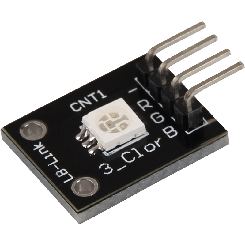
This LED module contains three different LEDs in the colors red, blue and green. These three LEDs are connected to each other via a common cathode, which means that they all share the same negative connection. The red LED requires a voltage of 1.8 V to light up, while the green and blue LEDs each require a voltage of 2.8 V. All LEDs operate at a current of 20 mA.
With this module, you can create a variety of color combinations by adjusting the brightness of the individual LEDs. By mixing red, green and blue, almost all colors of the visible spectrum can be created. The module is ideal for projects where visual signals, displays or decorative lighting effects are required.
The compact design allows easy integration into various circuits and projects. Whether you are a beginner or an experienced developer, this LED module offers a flexible and versatile solution for your lighting needs. Thanks to the clear color output and simple control, you can realize creative and impressive light installations.
| Technical Data | |
|---|---|
| Forward voltage [red] | 1,8 V |
| Forward voltage [green, blue] | 2,8 V |
| Forward current | 20 mA |
Series resistors:
Different series resistors are required depending on the color being controlled.
| Input voltage | Series resistor |
|---|---|
| red | 180 Ω |
| green | 100 Ω |
| blue | 100 Ω |
Pin assignment


| Arduino | Sensor |
|---|---|
| Pin 10 | LED RED |
| Pin 11 | LED GREEN |
| Pin 12 | LED BLUE |
| GND | GND |
1. Code example: ON/OFF
This code example shows how the integrated LEDs can be changed alternately, every 3 seconds, by means of a definable output pin.
To load the following code example onto your Arduino, we recommend using the Arduino IDE. In the IDE, you can select the appropriate port and board for your device.
Copy the code below into your IDE. To upload the code to your Arduino, simply click on the upload button.
int led_red = 10; // Pin for red
int led_green = 11; // Pin for green
int led_blue = 12; // Pin for blue

void setup() {
  // Initialization of output pins for the LEDs
  pinMode(led_red, OUTPUT);
  pinMode(led_green, OUTPUT);
  pinMode(led_blue, OUTPUT);
}
// Main program loop
void loop () {
  digitalWrite(led_red, HIGH); // red LED is switched on
  digitalWrite(led_green, LOW); // green LED is switched off
  digitalWrite(led_blue, LOW); // blue LED is switched off
  delay(3000); // Wait for 3 seconds

  digitalWrite(led_red, LOW); // red LED is switched off
  digitalWrite(led_green, HIGH); // green LED is switched on
  digitalWrite(led_blue, LOW); // blue LED is switched off
  delay(3000); // Wait for 3 seconds

  digitalWrite(led_red, LOW); // red LED is switched off
  digitalWrite(led_green, LOW); // green LED is switched off
  digitalWrite(led_blue, HIGH); // blue LED is switched on
  delay(3000); // Wait for 3 seconds
}
2. Code example: PWM
Pulse width modulation [PWM] can be used to regulate the brightness of an LED - in this process, the LED is switched on and off at specific time intervals, with the ratio of the switch-on and switch-off times corresponding to a relative brightness. Due to the inertia of human vision, human eyes interpret such on/off behavior as a change in brightness. More information on this topic can be found in this article by Analog IC Tips.
Several LEDs are integrated in this module - different colors can thus be created by superimposing different brightness levels. This is shown in the following code example.
To load the following code example onto your Arduino, we recommend using the Arduino IDE. In the IDE, you can select the appropriate port and board for your device.
Copy the code below into your IDE. To upload the code to your Arduino, simply click on the upload button.
int led_red = 10; // Pin for red
int led_green = 11; // Pin for green
int led_blue = 12; // Pin for blue

void setup() {
  // Initialization of output pins for the LEDs
  pinMode(led_red, OUTPUT);
  pinMode(led_green, OUTPUT);
  pinMode(led_blue, OUTPUT);
}
void loop() {
   // Within a For loop, the three LEDs are given different PWM values
   // This creates a color gradient in which different colors are created by mixing different
   // brightness levels of the two integrated LEDs, different colors are created
   for(int i = 255; i > 0; i--) {
       analogWrite(led_blue, i);
       analogWrite(led_green, 255 - i);
       analogWrite(led_red, 128 - i);
       delay(10);
   }
   // In the second For loop, the color gradient is run backwards
   for(int i = 0; i < 255; i++) {
      analogWrite(led_blue, i);
      analogWrite(led_green, 255 - i);
      analogWrite(led_red, 128 - i);
      delay(10);
   }
}
This LED module contains three different LEDs in the colors red, blue and green. These three LEDs are connected to each other via a common cathode, which means that they all share the same negative connection. The red LED requires a voltage of 1.8 V to light up, while the green and blue LEDs each require a voltage of 2.8 V. All LEDs operate at a current of 20 mA.
With this module, you can create a variety of color combinations by adjusting the brightness of the individual LEDs. By mixing red, green and blue, almost all colors of the visible spectrum can be created. The module is ideal for projects where visual signals, displays or decorative lighting effects are required.
The compact design allows easy integration into various circuits and projects. Whether you are a beginner or an experienced developer, this LED module offers a flexible and versatile solution for your lighting needs. Thanks to the clear color output and simple control, you can realize creative and impressive light installations.
| Technical Data | |
|---|---|
| Forward voltage [red] | 1,8 V |
| Forward voltage [green, blue] | 2,8 V |
| Forward current | 20 mA |
Series resistors:
Depending on the input voltage, series resistors are required.
| Input voltage | Series resistor |
|---|---|
| 3,3 V [red] | 180 Ω |
| 3,3 V [green] | 100 Ω |
| 3,3 V [blue] | 100 Ω |
| 5 V [red] | 180 Ω |
| 5 V [green] | 100 Ω |
| 5V [blue] | 100 Ω |
Pin assignment

| Raspberry Pi | Sensor |
|---|---|
| GPIO 25 [Pin 22] | LED RED |
| GPIO 24 [Pin 18] | LED GREEN |
| GPIO 23 [Pin 16] | LED BLUE |
| GND [Pin 6] | GND |
Code example (ON/OFF)
This code example shows how the integrated LEDs can be changed alternately, every 3 seconds, by means of a definable output pin.
from gpiozero import LED
import time

# Declaration of the LEDs on their corresponding GPIO pins
led_red = LED(25)
led_green = LED(24)
led_blue = LED(23)

print("LED test [press CTRL+C to end the test]")

# Main program loop
try:
    while True:
        print("LED RED on for 3 seconds")
        led_red.on()
        led_green.off()
        led_blue.off()
        time.sleep(3)  # Wait mode for 3 seconds

        print("LED GREEN on for 3 seconds")
        led_red.off()
        led_green.on()
        led_blue.off()
        time.sleep(3)  # Wait mode for 3 seconds

        print("LED BLUE on for 3 seconds")
        led_red.off()
        led_green.off()
        led_blue.on()
        time.sleep(3)  # Wait mode for 3 seconds

# Clean up after the program has been completed
except KeyboardInterrupt:
    print("Program terminated by user")
    # gpiozero automatically takes care of the cleanup at the end of the program
Code example (PWM)
Pulse width modulation [PWM] can be used to regulate the brightness of an LED - in this process, the LED is switched on and off at specific time intervals, with the ratio of the switch-on and switch-off times corresponding to a relative brightness. Due to the inertia of human vision, human eyes interpret such on/off behavior as a change in brightness. More information on this topic can be found in this article by Analog IC Tips.
Several LEDs are integrated in this module - different colors can thus be created by superimposing different brightness levels. This is shown in the following code example.
from gpiozero import PWMLED
import time
import random

# Definition of the PWMLEDs for each color
led_red = PWMLED(25)
led_green = PWMLED(24)
led_blue = PWMLED(23)

# This function generates the actual color
# The color intensity can be changed using the respective color variable
# After the color has been set, "time.sleep" is used to define the time for which the color in question is to be displayed
def led_farbe(red, green, blue, pause):
    led_red.value = red
    led_green.value = green
    led_blue.value = blue
    time.sleep(pause)

    # Reset to zero after the run
    led_red.value = 0
    led_green.value = 0
    led_blue.value = 0

print("LED test [press CTRL+C to end the test]")

# Main program loop:
# This has the task of creating a separate variable for each individual color and using a For loop to run through the color intensity of each individual color from 0-100%
# A color gradient is created by mixing the different brightness levels of the respective colors
try:
    while True:
        for x in range(0, 2):
            for y in range(0, 2):
                for z in range(0, 2):
                    print(x, y, z)
                    for i in range(0, 101):
                        # Set the LED color based on the current loop cycle
                        led_farbe(x * i / 100, y * i / 100, z * i / 100, 0.02)

# Clean-up work after the program has been completed
except KeyboardInterrupt:
    print("Program terminated by user")
This LED module contains three different LEDs in the colors red, blue and green. These three LEDs are connected to each other via a common cathode, which means that they all share the same negative connection. The red LED requires a voltage of 1.8 V to light up, while the green and blue LEDs each require a voltage of 2.8 V. All LEDs operate at a current of 20 mA.
With this module, you can create a variety of color combinations by adjusting the brightness of the individual LEDs. By mixing red, green and blue, almost all colors of the visible spectrum can be created. The module is ideal for projects where visual signals, displays or decorative lighting effects are required.
The compact design allows easy integration into various circuits and projects. Whether you are a beginner or an experienced developer, this LED module offers a flexible and versatile solution for your lighting needs. Thanks to the clear color output and simple control, you can realize creative and impressive light installations.
| Technical Data | |
|---|---|
| Forward voltage [red] | 1,8 V |
| Forward voltage [green, blue] | 2,8 V |
| Forward current | 20 mA |
Series resistors:
Depending on the input voltage, series resistors are required.
| Input voltage | Series resistor |
|---|---|
| 3,3 V [red] | 180 Ω |
| 3,3 V [green] | 100 Ω |
| 3,3 V [blue] | 100 Ω |
| 5 V [red] | 180 Ω |
| 5 V [green] | 100 Ω |
| 5V [blue] | 100 Ω |
Pin assignment

| Micro:Bit | Sensor |
|---|---|
| Pin 1 | LED RED |
| Pin 2 | LED GREEN |
| Pin 0 | LED BLUE |
| GND | GND |
This example turns on the LEDs depending on which button is pressed.
		input.onButtonPressed(Button.A, function () {
		    pins.digitalWritePin(DigitalPin.P2, 1)
		    pins.digitalWritePin(DigitalPin.P0, 0)
		    pins.digitalWritePin(DigitalPin.P1, 0)
		})
		input.onButtonPressed(Button.AB, function () {
		    pins.digitalWritePin(DigitalPin.P1, 1)
		    pins.digitalWritePin(DigitalPin.P2, 0)
		    pins.digitalWritePin(DigitalPin.P0, 0)
		})
		input.onButtonPressed(Button.B, function () {
		    pins.digitalWritePin(DigitalPin.P0, 1)
		    pins.digitalWritePin(DigitalPin.P2, 0)
		    pins.digitalWritePin(DigitalPin.P1, 0)
		})
Example program download
This LED module contains three different LEDs in the colors red, blue and green. These three LEDs are connected to each other via a common cathode, which means that they all share the same negative connection. The red LED requires a voltage of 1.8 V to light up, while the green and blue LEDs each require a voltage of 2.8 V. All LEDs operate at a current of 20 mA.
With this module, you can create a variety of color combinations by adjusting the brightness of the individual LEDs. By mixing red, green and blue, almost all colors of the visible spectrum can be created. The module is ideal for projects where visual signals, displays or decorative lighting effects are required.
The compact design allows easy integration into various circuits and projects. Whether you are a beginner or an experienced developer, this LED module offers a flexible and versatile solution for your lighting needs. Thanks to the clear color output and simple control, you can realize creative and impressive light installations.
| Technical Data | |
|---|---|
| Forward voltage [red] | 1,8 V |
| Forward voltage [green, blue] | 2,8 V |
| Forward current | 20 mA |
Series resistors:
Depending on the input voltage, series resistors are required.
| Input voltage | Series resistor |
|---|---|
| red | 180 Ω |
| green | 100 Ω |
| blue | 100 Ω |
Pin assignment

| Raspberry Pi Pico | Sensor |
|---|---|
| GPIO27 | LED RED |
| GPIO28 | LED GREEN |
| GPIO26 | LED BLUE |
| GND | GND |
1. Code example: ON/OFF
This code example shows how the integrated LEDs can be changed alternately, every 3 seconds, by means of a definable output pin.
To load the following code example onto your Pico, we recommend using the Thonny IDE. All you have to do first is go to Run > Configure interpreter ... > Interpreter > Which kind of interpreter should Thonny use for running your code? and select MicroPython (Raspberry Pi Pico).
Now copy the code below into your IDE and click on Run.
# Load libraries
from machine import Pin, PWM
from time import sleep

# Initialization of GPIO26, GPIO27 and GPIO28 as output
Green = Pin(28, Pin.OUT)
Red = Pin(27, Pin.OUT)
Blue = Pin(26, Pin.OUT)

while True:
    # green light
    Green.value(1)
    Red.value(0)
    Blue.value(0)
    sleep(3)
    # red light
    Green.value(0)
    Red.value(1)
    Blue.value(0)
    sleep(3)
    # blue light
    Green.value(0)
    Red.value(0)
    Blue.value(1)
    sleep(3)
    # Switch off LED
    Green.value(0)
    Red.value(0)
    Blue.value(0)
    sleep(3)
    # yellow light
    Green.value(1)
    Red.value(1)
    Blue.value(0)
    sleep(3)
    # turquoise light
    Green.value(1)
    Red.value(0)
    Blue.value(1)
    sleep(3)
    # pink light
    Green.value(0)
    Red.value(1)
    Blue.value(1)
    sleep(3)
    # Switch off LED
    Green.value(0)
    Red.value(0)
    Blue.value(0)
    sleep(3)
2. Code example: PWM
By means of pulse width modulation [PWM], the brightness of an LED can be regulated - in this process, the LED is switched on and off at specific time intervals, with the ratio of the switch-on and switch-off time corresponding to a relative brightness. Due to the inertia of human vision, human eyes interpret such on/off behavior as a change in brightness. More information on this topic can be found in this article from mikrokontroller.net.
Several LEDs are integrated in this module - different colors can thus be created by superimposing different brightness levels. This is shown in the following code example.
To load the following code example onto your Pico, we recommend using the Thonny IDE. All you have to do first is go to Run > Configure interpreter ... > Interpreter > Which kind of interpreter should Thonny use for running your code? and select MicroPython (Raspberry Pi Pico).
Now copy the code below into your IDE and click on Run.
# Load libraries
import machine
import math

# Initialization of GPIO26, GPIO27 and GPIO28 as PWM Pin
ledRed = machine.PWM(machine.Pin(27))
ledRed.freq(1000)
ledBlue = machine.PWM(machine.Pin(26))
ledBlue.freq(1000)
ledGreen = machine.PWM(machine.Pin(28))
ledGreen.freq(1000)

# Definition of a 3 digit list
RBG = [0,0,0]

# Function: Color space calculation for red, green and blue
# Green is 120° offset from red
# Blue is 240° offset from red
def sinColour(number):
    a = (math.sin(math.radians(number))+1)*32768
    b = (math.sin(math.radians(number+120))+1)*32768
    c = (math.sin(math.radians(number+240))+1)*32768
    RBG = (int(a),int(b),int(c))
    return RBG

# Endless loop where the color value for all 3 colors is shifted again and again by 0.01
a = 0

while True:
    RBG = sinColour(a)
    a += 0.01
    if a == 360:
        a = 0
    ledRed.duty_u16(RBG[0])
    ledBlue.duty_u16(RBG[1])
    ledGreen.duty_u16(RBG[2])