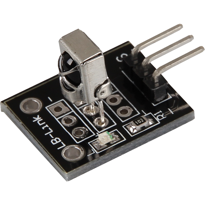
KY-022 Infrared receiver
This module can receive infrared signals and outputs them at the signal output as a digital sequence.
- Arduino
- Raspberry Pi
- Raspberry Pi Pico
- Micro:Bit
This module can receive infrared signals and converts them into digital signals that are emitted at the output. When an infrared signal is detected, an integrated LED on the module flashes briefly, providing visual confirmation of signal reception. It is ideal for projects where infrared remote controls or other infrared signals are used. Thanks to its simple handling and reliable signal processing, the module can be easily integrated into various electronics projects, for example to implement remote controls or transmit data wirelessly.
| Technical Data | |
|---|---|
| Operating voltage | 3,3 V - 5 V |
| Operating current | 0,4 - 1,5 mA |
| Reception range | 18 m |
| Reception angle | ± 45 ° |
| Carrier frequency | 38 kHz |
Pin assignment


| Arduino | Receiver |
|---|---|
| Pin 2 | signal |
| 5 V | +V |
| GND | GND |
Code example
With the help of the two sensor modules KY-005 and KY-022 a system with infrared remote control and infrared receiver can be built. For this purpose, two Arduinos are required in addition to the two modules. These then act as transmitters and receivers of the signals.
With the help of the sensor module KY-022 an infrared receiver can be built. For this only the infrared receiver module and a single Arduino are needed. The Arduino acts as a receiver and outputs the signals to the serial console.
To load the following code example onto your Arduino, we recommend using the Arduino IDE. In the IDE, you can select the appropriate port and the correct board for your device. For the following code example an additional library is needed:
IRremote by Ken Shirriff | published under the MIT license.
You can easily add these libraries via the library manager of the Arduino IDE.
With infrared transmitter and receiver systems, there are different protocols in which the data can be sent and received. In the following example the modified SimpleReceiver example is used for receiving - the used library IRremote takes care of the conversion to the correct data sequence on its own. However, there are also other protocols/encodings within the library - these are marked in the documentation/code of the library. Documentation.
Please note: For the execution of the code example an additional file is necessary. This opens automatically as soon as you open the sample code from the IRremote library. Therefore, first open the example code via the following path: File > Examples > IRremote > SimpleReceiver
Now you can replace the example code with our modified example. To upload the code to the Arduino, simply click on the upload button.
/*
 * SimpleReceiver.cpp
 *
 * Demonstrates the reception of ONLY NEC protocol IR codes with IRremote.
 * If no protocol is defined, all protocols (except Bang&Olufsen) are active.
 *
 *  This file is part of Arduino-IRremote https://github.com/Arduino-IRremote/Arduino-IRremote.
 *
 ************************************************************************************
 * MIT License
 *
 * Copyright (c) 2020-2023 Armin Joachimsmeyer
 *
 * Permission is hereby granted, free of charge, to any person obtaining a copy
 * of this software and associated documentation files (the "Software"), to deal
 * in the Software without restriction, including without limitation the rights
 * to use, copy, modify, merge, publish, distribute, sublicense, and/or sell
 * copies of the Software, and to permit persons to whom the Software is furnished
 * to do so, subject to the following conditions:
 *
 * The above copyright notice and this permission notice shall be included in all
 * copies or substantial portions of the Software.
 *
 * THE SOFTWARE IS PROVIDED "AS IS", WITHOUT WARRANTY OF ANY KIND, EXPRESS OR IMPLIED,
 * INCLUDING BUT NOT LIMITED TO THE WARRANTIES OF MERCHANTABILITY, FITNESS FOR A
 * PARTICULAR PURPOSE AND NONINFRINGEMENT. IN NO EVENT SHALL THE AUTHORS OR COPYRIGHT
 * HOLDERS BE LIABLE FOR ANY CLAIM, DAMAGES OR OTHER LIABILITY, WHETHER IN AN ACTION OF
 * CONTRACT, TORT OR OTHERWISE, ARISING FROM, OUT OF OR IN CONNECTION WITH THE SOFTWARE
 * OR THE USE OR OTHER DEALINGS IN THE SOFTWARE.
 *
 ************************************************************************************
 */

#include <Arduino.h>

/*
 * Specify which protocol(s) should be used for decoding.
 * If no protocol is defined, all protocols (except Bang&Olufsen) are active.
 * This must be done before the #include <IRremote.hpp>.
 */
//#define DECODE_DENON        // Includes Sharp
//#define DECODE_JVC
//#define DECODE_KASEIKYO
//#define DECODE_PANASONIC    // Alias for DECODE_KASEIKYO
//#define DECODE_LG
#define DECODE_NEC          // Includes Apple and Onkyo. To enable all protocols, simply comment/uncomment this line.
//#define DECODE_SAMSUNG
//#define DECODE_SONY
//#define DECODE_RC5
//#define DECODE_RC6

//#define DECODE_BOSEWAVE
//#define DECODE_LEGO_PF
//#define DECODE_MAGIQUEST
//#define DECODE_WHYNTER
//#define DECODE_FAST

//#define DECODE_DISTANCE_WIDTH // Universal decoder for pulse distance protocols
//#define DECODE_HASH         // special decoder for all protocols

//#define DECODE_BEO          // This protocol must always be activated manually, i.e. it is NOT activated if no protocol is defined. It prevents the decoding of SONY!

//#define DEBUG               // Enable this to get lots of nice debug output from the decoders.

//#define RAW_BUFFER_LENGTH  750 // 750 is required for remote controls for air conditioning systems. Standard is 200.

/*
 * This include defines the current pin numbers for pins such as IR_RECEIVE_PIN, IR_SEND_PIN for many different boards and architectures
 */
#include "PinDefinitionsAndMore.h"
#include <IRremote.hpp> // Inclusion of the library

void setup() {
    Serial.begin(115200);
    while (!Serial)
        ; // Wait for Serial to become available. Will be optimized away for some cores.

    // Start the receiver and, if no 3rd parameter is specified, accept the LED_BUILTIN pin from the internal card definition as the standard feedback LED
    IrReceiver.begin(IR_RECEIVE_PIN, ENABLE_LED_FEEDBACK);
    Serial.println(F("KY-022: Infrared receiver test"));
    Serial.print(F("Ready to receive IR signals from protocols: "));
    printActiveIRProtocols(&Serial);
    Serial.println(F("at the pin " STR(IR_RECEIVE_PIN)));
}

void loop() {
    /*
     * Check whether received data is available and, if so, attempt to decode it.
     * The decoded result can be found in the IrReceiver.decodedIRData structure.
     *
     * e.g. command is in IrReceiver.decodedIRData.command
     * address is in command is in IrReceiver.decodedIRData.address
     * and up to 32 bits of raw data in IrReceiver.decodedIRData.decodedRawData
     */
    if (IrReceiver.decode()) {
        /*
         * Outputs a summary of the received data
         */
        if (IrReceiver.decodedIRData.protocol == UNKNOWN) {
            Serial.println(F("Received noise or an unknown (or not yet activated) protocol"));
            // We have an unknown protocol here, print extended information
            IrReceiver.printIRResultRawFormatted(&Serial, true);
            IrReceiver.resume(); // Do it here to get the raw data for the output with printIRResultRawFormatted().
        }
        else {
            IrReceiver.resume(); // Early release of the reception of the next IR frame
            IrReceiver.printIRResultShort(&Serial);
        }
    }
}
This module can receive infrared signals and converts them into digital signals that are emitted at the output. When an infrared signal is detected, an integrated LED on the module flashes briefly, providing visual confirmation of signal reception. It is ideal for projects where infrared remote controls or other infrared signals are used. Thanks to its simple handling and reliable signal processing, the module can be easily integrated into various electronics projects, for example to implement remote controls or transmit data wirelessly.
| Technical Data | |
|---|---|
| Operating voltage | 3,3 V - 5 V |
| Operating current | 0,4 - 1,5 mA |
| Reception range | 18 m |
| Reception angle | ± 45 ° |
| Carrier frequency | 38 kHz |
Pin assignment

| Raspberry Pi | Receiver |
|---|---|
| GPIO15 [Pin 10] | Signal |
| 3,3 V [Pin 17] | +V |
| GND [Pin 25] | GND |
Code example
For the initial setup, first open your config.txt file using the following command:
sudo nano /boot/config.txt
Add the following configurations to the end of the file here:
dtoverlay=gpio-ir,gpio_pin=15
dtoverlay=gpio-ir-tx,gpio_pin=14
With the key combination [CTRL+O] you can save the file. Confirm this with [Enter] and exit the editor with the combination [CTRL+X]. Now restart your Raspberry Pi with the following command:
sudo reboot
Now install the ir-keytable module:
sudo apt-get install ir-keytable -y
With the following command you can determine the device identification. This is necessary to be able to address the receiver in the further course:
ir-keytable
The first line of the output should look something like this:
Found /sys/class/rc/rc0/ (/dev/input/event0) with:
Here it can be read that we can address our receiver via the identification rc0. Therefore we start the reception now via the following command:
ir-keytable -t -s rc0
This module can receive infrared signals and converts them into digital signals that are emitted at the output. When an infrared signal is detected, an integrated LED on the module flashes briefly, providing visual confirmation of signal reception. It is ideal for projects where infrared remote controls or other infrared signals are used. Thanks to its simple handling and reliable signal processing, the module can be easily integrated into various electronics projects, for example to implement remote controls or transmit data wirelessly.
| Technical Data | |
|---|---|
| Operating voltage | 3,3 V - 5 V |
| Operating current | 0,4 - 1,5 mA |
| Reception range | 18 m |
| Reception angle | ± 45 ° |
| Carrier frequency | 38 kHz |
Pin assignment

| Micro:Bit | Receiver |
|---|---|
| Pin 1 | Signal |
| 3 V | +V |
| GND | GND |
Code example
For the following code example an additional library is needed:
pxt-makerbit-ir-receiver from 1010Technologies | published under the MIT License.
You must add this library to your IDE before using the code.
Add the library to your IDE by clicking on "Extensions" and entering the following URL in the search box: https://github.com/1010Technologies/pxt-makerbit-ir-receiver.git. Confirm the search with Enter.
		makerbit.onIrDatagram(function () {
		    if (true) {
		        basic.showIcon(IconNames.SmallHeart)
		    } else {
		        basic.showIcon(IconNames.Heart)
		    }
		})
		makerbit.connectIrReceiver(DigitalPin.P1, IrProtocol.NEC)
Sample program download
This module can receive infrared signals and converts them into digital signals that are emitted at the output. When an infrared signal is detected, an integrated LED on the module flashes briefly, providing visual confirmation of signal reception. It is ideal for projects where infrared remote controls or other infrared signals are used. Thanks to its simple handling and reliable signal processing, the module can be easily integrated into various electronics projects, for example to implement remote controls or transmit data wirelessly.
| Technical Data | |
|---|---|
| Operating voltage | 3,3 V - 5 V |
| Operating current | 0,4 - 1,5 mA |
| Reception range | 18 m |
| Reception angle | ± 45 ° |
| Carrier frequency | 38 kHz |
Pin assignment

| Raspberry Pi Pico | Receiver |
|---|---|
| GPIO16 | Signal |
| 3.3V | +V |
| GND | GND |
Code example
With the help of the two sensor modules KY-005 and KY-022 a system with infrared remote control and infrared receiver can be built. But here we will only use the transmitter with a pico.
To load the following code example onto your Pico, we recommend using the Thonny IDE. All you have to do first is go to Run > Configure interpreter ... > Interpreter > Which kind of interpreter should Thonny use for running your code? and select MicroPython (Raspberry Pi Pico).
The following library is used for the code example:
micropython-ir by Peter Hinch | published under the MIT license.
To use this library, you must download the ir_rx folder from the above library and load it onto the Pico in a folder called lib (you may need to create this).
In infrared transmission systems, there are different protocols in which the data can be sent. In the following example different protocols are used for sending. documentation
Afterwards you can copy the code below into your IDE and click on Run.
# Import libraries
import time
from machine import Pin
from ir_rx.nec import NEC_16  # NEC remote, 16 bit addresses

# Method to process received data
def callback(data, addr, ctrl):
    # Validate whether the data can be processed
    if data < 0:
        print('')
    else:
        # Output received data
        print("Received: \t Address:", hex(addr), "\tData:", hex(data))

print("KY-022 Infrared receiver test")

# Initialize IR receiver
ir = NEC_16(Pin(16, Pin.IN), callback)