KY-026 Analog flame sensor
This module can be used to detect open flames.
- Arduino
- Raspberry Pi
- Raspberry Pi Pico
- Micro:Bit
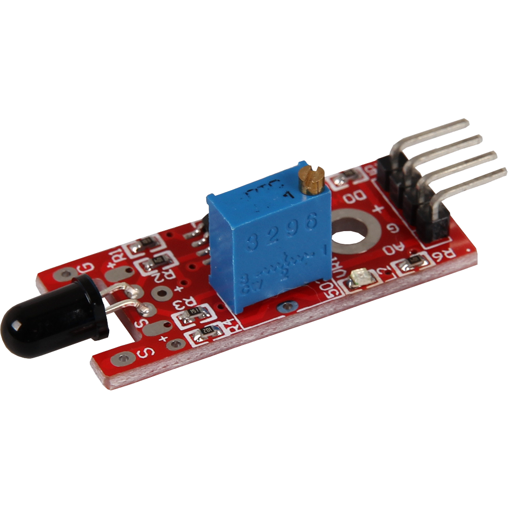
This module has been specially developed to detect open flames. The attached photodiode is particularly sensitive to the light spectrum generated by open flames. This enables the module to reliably detect and react to flames. It is ideal for safety applications, such as fire detection systems or fire alarms, where the fast and precise detection of flames is crucial. Easy integration into various systems makes this module a valuable component for fire protection and other applications where fire detection is important.
User note
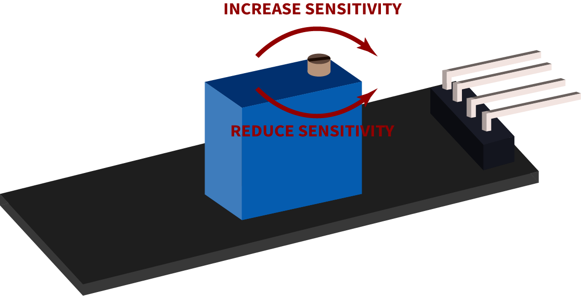
This sensor is ideally suited for threshold value measurement. This means that the sensor emits a digital high signal as soon as a threshold value set by the user on the rotary potentiometer is exceeded. It should be noted here that the digital signal is a comparison of the value set on the rotary potentiometer and the measured value on the sensor, which are then compared by the LM393 comparator installed on the board. The set value of the rotary potentiometer is the threshold value, which is used to define a logical high signal.
Digital output: If flames are detected, a signal is output here
Analog output: Direct measured value of the sensor unit
LED1: Indicates that the sensor is supplied with voltage
LED2: Indicates that flames have been detected
Functionality of the sensor
This sensor has two functional components on its circuit board: The front sensor unit, which physically measures the environment and outputs it as an analog signal to the second unit, the comparator. The comparator compares the measured value of the sensor with the value set on the rotary potentiometer and outputs a logical high signal on the digital pin and LED L1 if the value on the rotary potentiometer is exceeded.
Please note: The signal is inverted. If a high value is measured, this results in a lower voltage value at the analog output.
The rotary potentiometer can be set as follows:
Pin assignment


| Arduino | Sensor |
|---|---|
| 5 V | +V |
| GND | GND |
| Pin 3 | Digital Signal |
| Pin A0 | Analog Signal |
Code example
The program reads the current voltage value which can be measured at the analog output and outputs it to the serial interface. In addition, the state of the digital pin is also indicated in the console, which means whether the value has fallen below the limit or not.
To load the following code example onto your Arduino, we recommend using the Arduino IDE. In the IDE, you can select the appropriate port and board for your device.
Copy the code below into your IDE. To upload the code to your Arduino, simply click on the upload button.
// Declaration and initialization of the input pins
int analog_input = A0; // Analog output of the sensor
int digital_input = 3; // Digital output of the sensor

void setup () {
  pinMode(analog_input, INPUT);
  pinMode(digital_input, INPUT);
  Serial.begin(9600); // Serial output with 9600 bps
  Serial.println("KY-026 Flame detection");
}

// The program reads the current values of the input pins
// and prints them to the serial output
void loop () {
  float analog_value;
  int digital_value;

  // Current values are read out, converted to the voltage value...
  analog_value = analogRead(analog_input) * (5.0 / 1023.0);
  digital_value = digitalRead(digital_input);

  //... and printed at this point
  Serial.print("Analog voltage value: ");
  Serial.print(analog_value, 4);
  Serial.print(" V, \t Threshold value: ");

  if (digital_value == 1) {
      Serial.println("reached");
  }
  else {
      Serial.println("not yet reached");
  }
  Serial.println("----------------------------------------------------------------");
  delay(1000);
}
This module has been specially developed to detect open flames. The attached photodiode is particularly sensitive to the light spectrum generated by open flames. This enables the module to reliably detect and react to flames. It is ideal for safety applications, such as fire detection systems or fire alarms, where the fast and precise detection of flames is crucial. Easy integration into various systems makes this module a valuable component for fire protection and other applications where fire detection is important.
User note
This sensor is ideally suited for threshold value measurement. This means that the sensor emits a digital high signal as soon as a threshold value set by the user on the rotary potentiometer is exceeded. It should be noted here that the digital signal is a comparison of the value set on the rotary potentiometer and the measured value on the sensor, which are then compared by the LM393 comparator installed on the board. The set value of the rotary potentiometer is the threshold value, which is used to define a logical high signal.
Digital output: If flames are detected, a signal is output here
Analog output: Direct measured value of the sensor unit
LED1: Indicates that the sensor is supplied with voltage
LED2: Indicates that flames have been detected
Functionality of the sensor
This sensor has two functional components on its circuit board: The front sensor unit, which physically measures the environment and outputs it as an analog signal to the second unit, the comparator. The comparator compares the measured value of the sensor with the value set on the rotary potentiometer and outputs a logical high signal on the digital pin and LED L1 if the value on the rotary potentiometer is exceeded.
Please note: The signal is inverted. If a high value is measured, this results in a lower voltage value at the analog output.
The rotary potentiometer can be set as follows:
Pin assignment

| Raspberry Pi | Sensor |
|---|---|
| GPIO 24 [Pin 18] | Digital Signal |
| 3,3 V [Pin 1] | +V |
| GND [Pin 6] | GND |
| - | Analog Signal |
| Sensor | KY-053 |
|---|---|
| Analog Signal | A0 |
| Digital Signal | - |
| +V | - |
| GND | - |
| Raspberry Pi | KY-053 |
|---|---|
| GPIO 3 [Pin 5] | SCL |
| GPIO 2 [Pin 3] | SDA |
| 3,3 V [Pin 1] | VDD |
| GND [Pin 6] | GND |
Analog sensor, therefore the following must be considered: The Raspberry Pi has, in contrast to the Arduino, no analog inputs or there is no ADC (analog digital converter) integrated in the chip of the Raspberry Pi. This limits the Raspberry Pi, if you want to use sensors, which do not output digital values, but a continuously changing value (example: potentiometer -> different position = different voltage value).
To avoid this problem, our sensor kit X40 contains the KY-053, a module with a 16-bit ADC, which you can use on the Raspberry to expand it with 4 analog inputs. This module is connected to the Raspberry Pi via I2C, takes over the analog measurement and transfers the value digitally to the Raspberry Pi.
So we recommend to connect the KY-053 module with the mentioned ADC in between for analog sensors of this set. You can find more information on the KY-053 Analog Digital Converter.
Code example
Attention! To use this module in combination with the KY-053 Analog-Digital-Converter, a virtual environment must be set up. All the necessary information can be found here.
#!/usr/bin/python
# coding=utf-8
import time
import board
import busio
import adafruit_ads1x15.ads1115 as ADS
from adafruit_ads1x15.analog_in import AnalogIn
import gpiozero

# Create the I2C bus
i2c = busio.I2C(board.SCL, board.SDA)

# Create the ADC object using the I2C bus
ads = ADS.ADS1115(i2c)

# Create single-ended input on channels
chan0 = AnalogIn(ads, ADS.P0)
chan1 = AnalogIn(ads, ADS.P1)
chan2 = AnalogIn(ads, ADS.P2)
chan3 = AnalogIn(ads, ADS.P3)

delayTime = 1
Digital_PIN = 24

input = gpiozero.DigitalInputDevice(Digital_PIN, pull_up=None, active_state=True)

while True:
    analog = '%.2f' % chan0.voltage

    # Output to the console
    if input.is_active == False:
        print ("Analog voltage value:", analog,"V, ","Limit value: not yet reached")
    else:
        print ("Analog voltage value:", analog, "V, ", "Limit value: reached")
        print ("---------------------------------------")

    time.sleep(delayTime)
This module has been specially developed to detect open flames. The attached photodiode is particularly sensitive to the light spectrum generated by open flames. This enables the module to reliably detect and react to flames. It is ideal for safety applications, such as fire detection systems or fire alarms, where the fast and precise detection of flames is crucial. Easy integration into various systems makes this module a valuable component for fire protection and other applications where fire detection is important.
User note
This sensor is ideally suited for threshold value measurement. This means that the sensor emits a digital high signal as soon as a threshold value set by the user on the rotary potentiometer is exceeded. It should be noted here that the digital signal is a comparison of the value set on the rotary potentiometer and the measured value on the sensor, which are then compared by the LM393 comparator installed on the board. The set value of the rotary potentiometer is the threshold value, which is used to define a logical high signal.
Digital output: If flames are detected, a signal is output here
Analog output: Direct measured value of the sensor unit
LED1: Indicates that the sensor is supplied with voltage
LED2: Indicates that flames have been detected
Functionality of the sensor
This sensor has two functional components on its circuit board: The front sensor unit, which physically measures the environment and outputs it as an analog signal to the second unit, the comparator. The comparator compares the measured value of the sensor with the value set on the rotary potentiometer and outputs a logical high signal on the digital pin and LED L1 if the value on the rotary potentiometer is exceeded.
Please note: The signal is inverted. If a high value is measured, this results in a lower voltage value at the analog output.
The rotary potentiometer can be set as follows:
Pin assignment

| Micro:Bit | Sensor |
|---|---|
| Pin 1 | Digital Signal |
| 3,3 V | +V |
| GND | GND |
| - | Analog Signal |
| Sensor | KY-053 |
|---|---|
| Analog Signal | A0 |
| Digital Signal | - |
| +V | - |
| GND | - |
| Micro:Bit | KY-053 |
|---|---|
| Pin 19 | SCL |
| Pin 20 | SDA |
| 3,3 V | VDD |
| GND | GND |
Analog sensor, therefore the following must be observed: The Micro:Bit has analog inputs or there is an ADC (analog digital converter) integrated in the chip of the Micro:Bit. However, these are only limited to 10-bit and therefore offer only a rather low accuracy for analog measurements.
To avoid this problem, our sensor kit X40 contains the KY-053, a module with a 16-bit ADC, which you can use on the Micro:Bit to expand it by 4 analog inputs. This is connected to the Micro:Bit via I2C, takes over the analog measurement and transfers the value digitally to the Micro:Bit.
Therefore we recommend to connect the KY-053 module with the mentioned ADC in between for analog sensors of this set. More information can be found on the KY-053 Analog Digital Converter information page KY-053 Analog Digital Converter.
Code example
The program uses the corresponding library from us to control the ADS1115 ADC. This has been published under the following link pxt-ads1115 under the MIT-License.
		pins.setPull(DigitalPin.P1, PinPullMode.PullUp)
		ADS1115.setMode(mode.Multi)
		ADS1115.setRate(rate.Rate5)
		ADS1115.setGain(gain.One)
		ADS1115.initADS1115(userInI2C.Gnd)
		basic.forever(function () {
		    serial.writeString("Analog Value: ")
		    serial.writeLine("" + (ADS1115.raw_to_v(ADS1115.read(0))))
		    if (pins.digitalReadPin(DigitalPin.P1) == 1) {
		        serial.writeLine("Flame detected!")
		    } else {
		        serial.writeLine("No flame detected")
		    }
		    serial.writeLine("_____________________________________")
		    basic.pause(1000)
		})
Sample program download
This module has been specially developed to detect open flames. The attached photodiode is particularly sensitive to the light spectrum generated by open flames. This enables the module to reliably detect and react to flames. It is ideal for safety applications, such as fire detection systems or fire alarms, where the fast and precise detection of flames is crucial. Easy integration into various systems makes this module a valuable component for fire protection and other applications where fire detection is important.
User note
This sensor is ideally suited for threshold value measurement. This means that the sensor emits a digital high signal as soon as a threshold value set by the user on the rotary potentiometer is exceeded. It should be noted here that the digital signal is a comparison of the value set on the rotary potentiometer and the measured value on the sensor, which are then compared by the LM393 comparator installed on the board. The set value of the rotary potentiometer is the threshold value, which is used to define a logical high signal.
Digital output: If flames are detected, a signal is output here
Analog output: Direct measured value of the sensor unit
LED1: Indicates that the sensor is supplied with voltage
LED2: Indicates that flames have been detected
Functionality of the sensor
This sensor has two functional components on its circuit board: The front sensor unit, which physically measures the environment and outputs it as an analog signal to the second unit, the comparator. The comparator compares the measured value of the sensor with the value set on the rotary potentiometer and outputs a logical high signal on the digital pin and LED L1 if the value on the rotary potentiometer is exceeded.
Please note: The signal is inverted. If a high value is measured, this results in a lower voltage value at the analog output.
The rotary potentiometer can be set as follows:
Pin assignment

| Raspberry Pi Pico | Sensor |
|---|---|
| GPIO26 (A0) | Analog Signal |
| GND | GND |
| 3 V | +V |
| GPIO18 | Digital Signal |
You can also use an ADC such as the KY-053. This ADC has a higher resolution than the internal ADC of the Raspberry Pi Pico, which means that the sensor can be analysed more accurately.
Code example
The program reads the current voltage value, which can be calculated by reading the analog output, and outputs it on the serial interface. In addition, the state of the digital pin is also indicated in the console. This indicates whether the limit value has been exceeded.
To load the following code example onto your Pico, we recommend using the Thonny IDE. All you have to do first is go to Run > Configure interpreter ... > Interpreter > Which kind of interpreter should Thonny use for running your code? and select MicroPython (Raspberry Pi Pico).
Now copy the code below into your IDE and click on Run.
# Load libraries
from machine import Pin, ADC
from time import sleep

# Initialization of ADC0
adc = ADC(0)
# Initialization of GPIO18 as input
digital = Pin(18,Pin.IN, Pin.PULL_UP)

print("KY-026 Flame detection")

# Endless loop for reading out the ADC
while True:
    raw_value = adc.read_u16()
    # Conversion from analog value to voltage
    Volt = round(raw_value* 3.3 / 65536, 2)
    digital_value = digital.value()

    # Serial output of the analog value and the calculated voltage
    print("Analog voltage value: " + str(Volt) + " V\t Threshold value: ", end="")

    # Query whether the digital value has changed with serial output
    if digital_value == 1:
        print("reached")
    else:
        print("not reached")

    print("----------------------------------------")
    sleep(2)