KY-10 Light barrier
When the light barrier of the module is interrupted, the signal coming from the module itself is also interrupted.
- Arduino
- Raspberry Pi
- Raspberry Pi Pico
- Micro:Bit
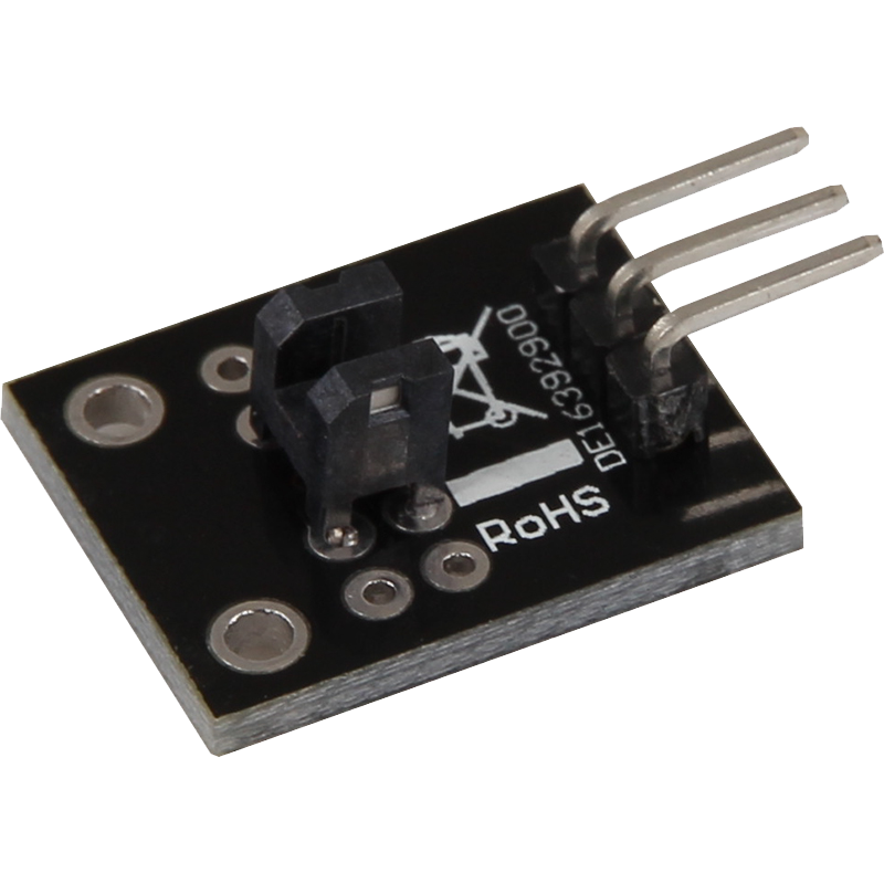
This module contains a light barrier that emits a signal as long as the light beam is not interrupted. If something blocks the light beam, the signal is also interrupted. This makes the module ideal for applications where the detection of an interruption or movement is required.
The photoelectric sensor operates at an operating voltage of 3.3 V to 5 V, making it compatible with a wide range of microcontrollers and single-board computers. Such modules are often used in security systems, counting devices or automated control systems to detect the presence or movement of an object.
Thanks to its simple operation and reliable detection, this module offers a practical solution for many projects where passage or movement monitoring is required. Its compact size and easy integration make it a useful component for a wide range of applications.
| Technical Data | |
|---|---|
| Operating voltage | 3,3 V - 5 V |
Pin assignment


| Arduino | Sensor |
|---|---|
| Pin 10 | signal |
| 5V | +V |
| GND | GND |
Code Example
To load the following code example onto your Arduino, we recommend using the Arduino IDE. In the IDE, you can select the appropriate port and board for your device.
Copy the code below into your IDE. To upload the code to your Arduino, simply click on the upload button.
int barrier = 10; // Declaration of the sensor input pin
int value; // Temporary variable

void setup () {
  pinMode(barrier, INPUT); // Initialization sensor pin
  digitalWrite(barrier, HIGH); // Activation of internal pull-up resistor
  Serial.begin(9600); // Initialization of the serial monitor
  Serial.println("KY-010 Light barrier test");
}

void loop () {
  // The current signal at the sensor is read out.
  value = digitalRead(barrier);
  // If a signal could be detected, this is displayed on the serial monitor.
  if (value == HIGH) {
    Serial.println("Signal detected");
    delay(100); // 100 ms break
  }
}
This module contains a light barrier that emits a signal as long as the light beam is not interrupted. If something blocks the light beam, the signal is also interrupted. This makes the module ideal for applications where the detection of an interruption or movement is required.
The photoelectric sensor operates at an operating voltage of 3.3 V to 5 V, making it compatible with a wide range of microcontrollers and single-board computers. Such modules are often used in security systems, counting devices or automated control systems to detect the presence or movement of an object.
Thanks to its simple operation and reliable detection, this module offers a practical solution for many projects where passage or movement monitoring is required. Its compact size and easy integration make it a useful component for a wide range of applications.
| Technical Data | |
|---|---|
| Operating voltage | 3,3 V - 5 V |
Pin assignment

| Raspberry Pi | Sensor |
|---|---|
| GPIO 24 [Pin 18] | Signal |
| 3.3 V [Pin 1] | +V |
| GND [Pin 6] | GND |
Code Example
This is a sample program that prints a console output when as signal is detected at the sensor.
from gpiozero import DigitalInputDevice
import time

# The input pin to which the sensor is connected is declared here.
# In addition, the PullUP resistor at the input is also deactivated
sensor = DigitalInputDevice(24, pull_up=False)

print("Sensor test [press CTRL+C to end the test]")

# This output function is executed when a signal is detected
def ausgabeFunktion():
    print("Signal recognized")

# When a signal is detected (rising signal edge), the output function is triggered
sensor.when_activated = ausgabeFunktion

# Main program loop
try:
    while True:
        time.sleep(1)

# Clean up after the program has been completed
except KeyboardInterrupt:
    print("Program was terminated by the user")
This module contains a light barrier that emits a signal as long as the light beam is not interrupted. If something blocks the light beam, the signal is also interrupted. This makes the module ideal for applications where the detection of an interruption or movement is required.
The photoelectric sensor operates at an operating voltage of 3.3 V to 5 V, making it compatible with a wide range of microcontrollers and single-board computers. Such modules are often used in security systems, counting devices or automated control systems to detect the presence or movement of an object.
Thanks to its simple operation and reliable detection, this module offers a practical solution for many projects where passage or movement monitoring is required. Its compact size and easy integration make it a useful component for a wide range of applications.
| Technical Data | |
|---|---|
| Operating voltage | 3,3 V - 5 V |
Pin assignment

| Micro:Bit | Sensor |
|---|---|
| Pin 1 | Signal |
| 3 V | +V |
| GND | GND |
Code example
		pins.setPull(DigitalPin.P1, PinPullMode.PullUp)
		basic.forever(function () {
		    serial.writeLine("" + (pins.digitalReadPin(DigitalPin.P1)))
		    if (pins.digitalReadPin(DigitalPin.P1) == 1) {
		        serial.writeLine("!!! Light barrier interrupted !!!")
		    } else {
		        serial.writeLine("Light barrier is not interrupted")
		    }
		    serial.writeLine("______________________________________")
		    basic.pause(1000)
		})
Sample program download
This module contains a light barrier that emits a signal as long as the light beam is not interrupted. If something blocks the light beam, the signal is also interrupted. This makes the module ideal for applications where the detection of an interruption or movement is required.
The photoelectric sensor operates at an operating voltage of 3.3 V to 5 V, making it compatible with a wide range of microcontrollers and single-board computers. Such modules are often used in security systems, counting devices or automated control systems to detect the presence or movement of an object.
Thanks to its simple operation and reliable detection, this module offers a practical solution for many projects where passage or movement monitoring is required. Its compact size and easy integration make it a useful component for a wide range of applications.
| Technical Data | |
|---|---|
| Operating voltage | 3,3 V - 5 V |
Pin assignment

| Raspberry Pi Pico | Sensor |
|---|---|
| GPIO18 | Signal |
| 3.3V | +V |
| GND | GND |
Code Example
This is a sample program that counts up and outputs serial text when a signal is detected at the sensor.
To load the following code example onto your Pico, we recommend using the Thonny IDE. All you have to do first is go to Run > Configure interpreter ... > Interpreter > Which kind of interpreter should Thonny use for running your code? and select MicroPython (Raspberry Pi Pico).
Now copy the code below into your IDE and click on Run.
# Load libraries
from machine import Pin, Timer

# Initialization of GPIO18 as input
sensor = Pin(18, Pin.IN, Pin.PULL_DOWN)

# Create timer
timer = Timer()

# Set counter to 0
counter = 0

print("KY-010 Light barrier test")

# Function to count movement in the barrier
def step(timer):
    global counter
    counter = counter + 1
    print(counter)

# Function to observe light barrier
def barrier(pin):
    # Debounce function: Set timer
    timer.init(mode=Timer.ONE_SHOT, period=100, callback=step)

# Initialization interrupt
sensor.irq(trigger=Pin.IRQ_FALLING, handler=barrier)