KY-018 Photoresistor
Contains an LDR resistor whose resistance value decreases with brighter environment.
- Arduino
- Raspberry Pi
- Raspberry Pi Pico
- Micro:Bit
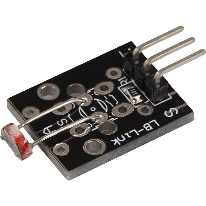
This module contains an LDR resistor (light sensor) whose resistance value decreases with increasing brightness. The resistance of the LDR can be determined using a voltage divider in which a known voltage is divided across a fixed resistance of 10 kΩ and the variable resistance of the LDR. By measuring the voltage in the voltage divider, the current resistance of the LDR and thus the light intensity can be calculated. The operating voltage of the module is between 3.3 V and 5 V, and the compact dimensions of 21 x 15 x 6 mm facilitate integration into various projects. This module is ideal for applications where the ambient brightness is to be detected, such as in automated lighting systems, brightness sensors and many other light-dependent applications. The exact calculation method for determining the brightness is described in the attached code examples.
Attention! This sensor is no longer included in revision 2 of the sensor kit and has been replaced by the KY-054 sensor!


| Technical data | |
|---|---|
| Operating voltage | 3,3 V - 5 V |
| Fixed known resistance | 10 kΩ |
| Dimensions | 21 x 15 x 6 mm |
Pin assignment


| Arduino | Sensor |
|---|---|
| Pin A5 | signal |
| 5 V | +V |
| GND | GND |
Code example
To load the following code example onto your Arduino, we recommend using the Arduino IDE. In the IDE, you can select the appropriate port and board for your device.
Copy the code below into your IDE. To upload the code to your Arduino, simply click on the upload button.
int photo_resistor = A5; // The input pin is declared here
// Define required variables
int rawValue;
float voltage;
float resistance;

void setup() {
    Serial.begin(9600); // Serial output in 9600 baud
    Serial.println("KY-018 Photoresistance test");
}

// The program measures the current voltage value at the sensor,
// calculates the current resistance value of the sensor from this and the known series resistance
// resistance value of the sensor and outputs the results to the serial output

void loop() {
    // Current voltage value is measured...
    rawValue = analogRead(photo_resistor);
    voltage = rawValue * (5.0/1023) * 1000;
    resistance = 10000 * (voltage / (5000.0 - voltage));

    // ... and issued on the serial interface
    Serial.print("Voltage level: ");
    Serial.print(voltage);
    Serial.print(" mV");
    Serial.print(",\t Resistance value: ");
    Serial.print(resistance);
    Serial.println(" Ohm");
    Serial.println("----------------------------------------------------------------");

    delay(500);
}
This module contains an LDR resistor (light sensor) whose resistance value decreases with increasing brightness. The resistance of the LDR can be determined using a voltage divider in which a known voltage is divided across a fixed resistance of 10 kΩ and the variable resistance of the LDR. By measuring the voltage in the voltage divider, the current resistance of the LDR and thus the light intensity can be calculated. The operating voltage of the module is between 3.3 V and 5 V, and the compact dimensions of 21 x 15 x 6 mm facilitate integration into various projects. This module is ideal for applications where the ambient brightness is to be detected, such as in automated lighting systems, brightness sensors and many other light-dependent applications. The exact calculation method for determining the brightness is described in the attached code examples.
Attention! This sensor is no longer included in revision 2 of the sensor kit and has been replaced by the KY-054 sensor!
| Technical data | |
|---|---|
| Operating voltage | 3,3 V - 5 V |
| Fixed known resistance | 10 kΩ |
| Dimensions | 21 x 15 x 6 mm |
Pin assignment

| Raspberry Pi | Sensor |
|---|---|
| - | Signal |
| 3,3 V [Pin 1] | +V |
| GND [Pin 6] | GND |
| Sensor | KY-053 |
|---|---|
| Signal | A0 |
| +V | - |
| GND | - |
| Raspberry Pi | KY-053 |
|---|---|
| 3,3 V [Pin 1] | +V |
| GND [Pin 6] | GND |
| GPIO 3 [Pin 5] | SCL |
| GPIO 2 [Pin 3] | SDA |
Analog sensor, therefore the following must be considered: In contrast to the Arduino, the Raspberry Pi does not have any analog inputs or there is no ADC (analog digital converter) integrated in the chip of the Raspberry Pi. This limits the Raspberry Pi, if you want to use sensors, which do not output digital values, but a continuously changing value (example: potentiometer -> different position = different voltage value).
To avoid this problem, our sensor kit X40 contains the KY-053, a module with a 16-bit ADC, which you can use on the Raspberry to expand it with 4 analog inputs. This module is connected to the Raspberry Pi via I2C, takes over the analog measurement and transfers the value digitally to the Raspberry Pi.
Thus we recommend to connect the KY-053 module with the said ADC in between for analog sensors of this set. More information can be found on the KY-053 Analog Digital Converter information page.
Code example
The program uses the corresponding ADS1x15 and I2C Python libraries from Adafruit to control the ADS1115 ADC. These have been published at the following link https://github.com/adafruit/Adafruit_CircuitPython_ADS1x15 under the MIT license. The required libraries are not included in the download package below.
Please note that you need to enable I2C on your Raspberry Pi before using this example.
#!/usr/bin/python
# coding=utf-8

import time
import board
import busio
import adafruit_ads1x15.ads1115 as ADS
from adafruit_ads1x15.analog_in import AnalogIn
import math
# Create the I2C bus
i2c = busio.I2C(board.SCL, board.SDA)

# Create the ADC object using the I2C bus
ads = ADS.ADS1115(i2c)
voltageMax = 3.3
# Create single-ended input on channels
chan0 = AnalogIn(ads, ADS.P0)
chan1 = AnalogIn(ads, ADS.P1)
chan2 = AnalogIn(ads, ADS.P2)
chan3 = AnalogIn(ads, ADS.P3)


while True:
    resistance = chan0.voltage / (voltageMax - chan0.voltage) * 10000

    print("Voltage value: ",'%.2f' % chan0.voltage, "V, resistance: ",'%.2f' % resistance, "Ω")
    print("---------------------------------------------------")
    time.sleep(1)
This module contains an LDR resistor (light sensor) whose resistance value decreases with increasing brightness. The resistance of the LDR can be determined using a voltage divider in which a known voltage is divided across a fixed resistance of 10 kΩ and the variable resistance of the LDR. By measuring the voltage in the voltage divider, the current resistance of the LDR and thus the light intensity can be calculated. The operating voltage of the module is between 3.3 V and 5 V, and the compact dimensions of 21 x 15 x 6 mm facilitate integration into various projects. This module is ideal for applications where the ambient brightness is to be detected, such as in automated lighting systems, brightness sensors and many other light-dependent applications. The exact calculation method for determining the brightness is described in the attached code examples.
Attention! This sensor is no longer included in revision 2 of the sensor kit and has been replaced by the KY-054 sensor!
| Technical data | |
|---|---|
| Operating voltage | 3,3 V - 5 V |
| Fixed known resistance | 10 kΩ |
| Dimensions | 21 x 15 x 6 mm |
Pin assignment

| Micro:Bit | Sensor |
|---|---|
| - | Signal |
| 3,3 V | +V |
| GND | GND |
| Sensor | KY-053 |
|---|---|
| Signal | A0 |
| +V | - |
| GND | - |
| Micro:Bit | KY-053 |
|---|---|
| Pin 19 | SCL |
| Pin 20 | SDA |
| 3,3 V | +V |
| GND | GND |
Analog sensor, therefore the following must be observed: The Micro:Bit has analog inputs or there is an ADC (analog digital converter) integrated in the chip of the Micro:Bit. However, these are only limited to 10-bit and therefore offer only a rather low accuracy for analog measurements.
To avoid this problem, our sensor kit X40 contains the KY-053, a module with a 16-bit ADC, which you can use on the Micro:Bit to expand it by 4 analog inputs. This is connected to the Micro:Bit via I2C, takes over the analog measurement and transfers the value digitally to the Micro:Bit.
Therefore we recommend to connect the KY-053 module with the mentioned ADC in between for analog sensors of this set. More information can be found on the KY-053 Analog Digital Converter information page KY-053 Analog Digital Converter.
Code example
The program uses the corresponding library from us to control the ADS1115 ADC. This has been published under the following link pxt-ads1115 under the MIT-License.
		ADS1115.setMode(mode.Multi)
		ADS1115.setRate(rate.Rate5)
		ADS1115.setGain(gain.One)
		ADS1115.initADS1115(userInI2C.Gnd)
		basic.forever(function () {
		    serial.writeLine("" + (ADS1115.read(0)))
		    serial.writeLine("" + (ADS1115.raw_to_v(ADS1115.read(0))))
		    basic.pause(500)
		})
Sample program download
This module contains an LDR resistor (light sensor) whose resistance value decreases with increasing brightness. The resistance of the LDR can be determined using a voltage divider in which a known voltage is divided across a fixed resistance of 10 kΩ and the variable resistance of the LDR. By measuring the voltage in the voltage divider, the current resistance of the LDR and thus the light intensity can be calculated. The operating voltage of the module is between 3.3 V and 5 V, and the compact dimensions of 21 x 15 x 6 mm facilitate integration into various projects. This module is ideal for applications where the ambient brightness is to be detected, such as in automated lighting systems, brightness sensors and many other light-dependent applications. The exact calculation method for determining the brightness is described in the attached code examples.
Attention! This sensor is no longer included in revision 2 of the sensor kit and has been replaced by the KY-054 sensor!
| Technical data | |
|---|---|
| Operating voltage | 3,3 V - 5 V |
| Fixed known resistance | 10 kΩ |
| Dimensions | 21 x 15 x 6 mm |
Pin assignment

| Raspberry Pi Pico | Sensor |
|---|---|
| 3,3 V | +V |
| GND | GND |
| GPIO26 (A0) | Signal |
You can also use an ADC such as the KY-053. This ADC has a higher resolution than the internal ADC of the Raspberry Pi Pico, which means that the sensor can be analysed more accurately.
Code example
The program measures the current voltage value at the sensor, calculates the current resistance value of the sensor from this and the known series resistance and outputs the results via serial output.
To load the following code example onto your Pico, we recommend using the Thonny IDE. All you have to do first is go to Run > Configure interpreter ... > Interpreter > Which kind of interpreter should Thonny use for running your code? and select MicroPython (Raspberry Pi Pico).
Now copy the code below into your IDE and click on Run.
# Load libraries
from machine import ADC
import math
from time import sleep

# Initialization of the ADC0 (GPIO26)
adc = ADC(0)

print("KY-018 Resistance measurement")

while True:
    # Read ADC0 as a decimal number
    read = adc.read_u16()
    # Calculate voltage
    voltage = read * (3.3 / 65536)
    # Conversion from voltage to resistance
    resistance = ((voltage / 3.3) * 10000) / (1 - (voltage / 3.3))
    # Serial output of the calculated values
    print("Voltage value: ", round(voltage, 2), "V\t Resistance:", round(resistance, 2), "Ohm")
    sleep(1)