KY-053 Analog Digital Converter
With the appropriate commands on the I2C bus, analog voltage values can be measured with up to 16-bit accuracy on up to 4 inputs.
- Arduino
- Raspberry Pi
- Raspberry Pi Pico
- Micro:Bit
The analog-to-digital converter (ADC) makes it possible to measure analog voltage values on up to 4 inputs with high precision. Corresponding commands can be sent via the I2C bus to carry out these measurements. The measured values are then coded and output to the I2C bus.
With a resolution of up to 16 bits, very precise measurements can be carried out. The ADC can program different sampling rates, which makes it flexible for different applications. It operates in a voltage range from 2 V to 5.5 V and can measure input voltages up to the operating voltage.
Easy integration via the I2C interface and the ability to use multiple ADC channels make this converter ideal for projects that require precise voltage measurements. Applications could include data acquisition, sensor monitoring or various electronics projects where accurate analog measurements are required. The low operating current of typically 150μA also makes it suitable for energy-efficient applications.
| Technical Data | |
|---|---|
| Interface | I2C |
| ADC channels | 4 |
| Resolution per Channel | 16 Bit |
| Programmable sampling rate | 8 to 860 SPS |
| Operating Voltage | 2 V to 5.5 V |
| Analog Input Voltage | 0 V to Operating Voltage |
| I2C logic voltage | 0 V to 5.5 V |
| I2C Address | 0x48 to 0x4B |
| Typical Operating Current | 150 μA |
A corresponding library is required for this module - see code examples below.
Changing the I2C address
This analog to digital converter (or in short ADC) has not only one I2C address. This is an ADC which can have 4 different I2C addresses. These can be chosen freely but in the further course the standard address 0x48 is used.
In the following table you can see all possible addresses and how they can be reached. Here is mainly to note that the ADDR pin of the ADC is responsible for the change of the address.
| From | To | Address |
|---|---|---|
| ADDR Pin | GND Pin | 0x48 |
| ADDR Pin | VDD Pin | 0x49 |
| ADDR Pin | SDA Pin | 0x4A |
| ADDR Pin | SCL Pin | 0x4B |
Pin assignment
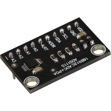
The pin assignment is printed on the module board


| Arduino | Sensor |
|---|---|
| 5V | + V |
| GND | GND |
| Pin A5 | SCL |
| Pin A4 | SDA |
| - | ADDR |
| - | ALRT |
| - | A0 |
| - | A1 |
| - | A2 |
| - | A3 |
Code example
The Arduino boards already have an integrated 10 bit ADC with 6 channels. If more channels, or a higher accuracy, are needed, the Arduino can be extended by 4 ADC channels with 16-bit accuracy using the KY-053 Analog Digital Converter Module.
To load the following code example onto your Arduino, we recommend using the Arduino IDE. In the IDE, you can select the appropriate port and the correct board for your device.
The following libraries are also used for the code example:
Adafruit ADS1X15 from Adafruit | published under the BSD-License
You can easily add these libraries via the library manager of the Arduino IDE. Then copy the code below into your IDE. To upload the code to the Arduino, simply click on the upload button.
#include <Adafruit_ADS1X15.h>
#include <math.h>

// ADS1115 module is initialized - all further operations with
// ADC can be carried out using the “ads” object.
Adafruit_ADS1115 ads;

void setup() {
  // Initialize serial monitor
  Serial.begin(9600);
  Serial.println("The values of the analog inputs of the ADS1115 (A0..A3) are read out and output");
  Serial.println("ADC Range: +/- 6.144V (1 bit = 0.1875mV)");

  // This module has signal amplifiers on its analog inputs,
  // whose amplification can be configured in the ranges below via software.
  // This is necessary if a certain voltage range is expected as a measurement result
  // expected as a measurement result and thus obtain a higher resolution of the signal.
  // ADS1115
  // -------
  ads.setGain(GAIN_TWOTHIRDS); // 2 / 3x gain +/- 6.144V 1 bit = 0.1875mV
  // ads.setGain(GAIN_ONE); // 1x gain +/- 4.096V 1 bit = 0.125mV
  // ads.setGain(GAIN_TWO); // 2x gain +/- 2.048V 1 bit = 0.0625mV
  // ads.setGain(GAIN_FOUR); // 4x gain +/- 1.024V 1 bit = 0.03125mV
  // ads.setGain(GAIN_EIGHT); // 8x gain +/- 0.512V 1 bit = 0.015625mV
  // ads.setGain(GAIN_SIXTEEN); // 16x gain +/- 0.256V 1 bit = 0.0078125mV

  ads.begin();
}

void loop() {
  uint16_t adc0, adc1, adc2, adc3;
  float voltage0, voltage1, voltage2, voltage3;
  float gain_conversion_factor;

  // The “ads.readADC_SingleEnded (0)” command is the actual process that starts the measurement in the ADC.
  // The “0” as a variable for this function defines the channel to be measured.
  // If, for example, the third channel is to be measured, the “0” must be replaced by “3”.
  adc0 = ads.readADC_SingleEnded(0);
  adc1 = ads.readADC_SingleEnded(1);
  adc2 = ads.readADC_SingleEnded(2);
  adc3 = ads.readADC_SingleEnded(3);

  // Conversion of the recorded values into a voltage
  voltage0 = ads.computeVolts(adc0);
  voltage1 = ads.computeVolts(adc1);
  voltage2 = ads.computeVolts(adc2);
  voltage3 = ads.computeVolts(adc3);

  // Output of the values on the serial interface
  Serial.print ("A0: "); Serial.print (voltage0); Serial.println (" V");
  Serial.print ("A1: "); Serial.print (voltage1); Serial.println (" V");
  Serial.print ("A2: "); Serial.print (voltage2); Serial.println (" V");
  Serial.print ("A3: "); Serial.print (voltage3); Serial.println (" V");
  Serial.println ("------------------------");

  delay (1000);
}
The analog-to-digital converter (ADC) makes it possible to measure analog voltage values on up to 4 inputs with high precision. Corresponding commands can be sent via the I2C bus to carry out these measurements. The measured values are then coded and output to the I2C bus.
With a resolution of up to 16 bits, very precise measurements can be carried out. The ADC can program different sampling rates, which makes it flexible for different applications. It operates in a voltage range from 2 V to 5.5 V and can measure input voltages up to the operating voltage.
Easy integration via the I2C interface and the ability to use multiple ADC channels make this converter ideal for projects that require precise voltage measurements. Applications could include data acquisition, sensor monitoring or various electronics projects where accurate analog measurements are required. The low operating current of typically 150μA also makes it suitable for energy-efficient applications.
| Technical Data | |
|---|---|
| Interface | I2C |
| ADC channels | 4 |
| Resolution per Channel | 16 Bit |
| Programmable sampling rate | 8 to 860 SPS |
| Operating Voltage | 2 V to 5.5 V |
| Analog Input Voltage | 0 V to Operating Voltage |
| I2C logic voltage | 0 V to 5.5 V |
| I2C Address | 0x48 to 0x4B |
| Typical Operating Current | 150 μA |
A corresponding library is required for this module - see code examples below.
Changing the I2C address
This analog to digital converter (or in short ADC) has not only one I2C address. This is an ADC which can have 4 different I2C addresses. These can be chosen freely but in the further course the standard address 0x48 is used.
In the following table you can see all possible addresses and how they can be reached. Here is mainly to note that the ADDR pin of the ADC is responsible for the change of the address.
| From | To | Address |
|---|---|---|
| ADDR Pin | GND Pin | 0x48 |
| ADDR Pin | VDD Pin | 0x49 |
| ADDR Pin | SDA Pin | 0x4A |
| ADDR Pin | SCL Pin | 0x4B |
Pin assignment
The pin assignment is printed on the module board

| Raspberry Pi | Sensor |
|---|---|
| 3.3 V | + V |
| GND | GND |
| GPIO 2 [pin 3] | SCL |
| GPIO 3 [pin 5] | SDA |
| - | ADDR |
| - | ALRT |
| - | A0 |
| - | A1 |
| - | A2 |
| - | A3 |
Code example
Unlike the Arduino, the Raspberry Pi has neither analog inputs nor an integrated analog-digital converter. This limits the Raspberry Pi when using analog sensors. To still use analog sensors on the Raspberry Pi, the Raspberry Pi can be extended by 4 ADC channels with 16-bit accuracy with our KY-053 Analog Digital Converter Module.
The program uses the corresponding ADS1x15 and I2C Python libraries from Adafruit to control the ADS1115 ADC. These were found under the following link https://github.com/adafruit/Adafruit_CircuitPython_ADS1x15 under the MIT license released. The required libraries are ** not ** included in the download package below.
First you need to enable I2C on your Raspberry Pi. To open the configuration, enter the following command:
sudo raspi-config
Select 3 Interface Options → I4 I2C and activate the I2C interface. You have now successfully activated I2C. The analog-to-digital converter can now be reached under the I2C address 0x48, which is set by default for this sensor. The I2C address will be different if you have already configured it before configuring your Raspberry Pi.
Now install pip3 with the following command:
sudo apt-get install python3-pip
The next step is to set up the virtual environment. To do this, enter the following commands:
mkdir dein_projekt
cd dein_projekt
python -m venv --system-site-packages env
source env/bin/activate
Use the following commands to download and install the adafruit-circuitpython-ads1x15 library.
pip3 install adafruit-circuitpython-ads1x15
After you have downloaded the library, you only need to enter the following command...
nano ADS1115.py
... to create a new file on your Raspberry Pi and then copy the following code into the file you have just created.
import time
import board
import busio
import adafruit_ads1x15.ads1115 as ADS
from adafruit_ads1x15.analog_in import AnalogIn

# Create the I2C bus
i2c = busio.I2C (board.SCL, board.SDA)

# Create the ADC object using the I2C bus
ads = ADS.ADS1115 (i2c)

# Create single-ended input on channels
chan0 = AnalogIn (ads, ADS.P0)
chan1 = AnalogIn (ads, ADS.P1)
chan2 = AnalogIn (ads, ADS.P2)
chan3 = AnalogIn (ads, ADS.P3)


while True:
    print ("channel 0:", "{:> 5} \ t {:> 5.3f}". format (chan0.value, chan0.voltage))
    print ("channel 1:", "{:> 5} \ t {:> 5.3f}". format (chan1.value, chan1.voltage))
    print ("channel 2:", "{:> 5} \ t {:> 5.3f}". format (chan2.value, chan2.voltage))
    print ("channel 3:", "{:> 5} \ t {:> 5.3f}". format (chan3.value, chan3.voltage))
    print ("----------------------------------------------- ---- ")
    time.sleep (1)
You can then start this with the following command:
python3 KY053.py
The analog-to-digital converter (ADC) makes it possible to measure analog voltage values on up to 4 inputs with high precision. Corresponding commands can be sent via the I2C bus to carry out these measurements. The measured values are then coded and output to the I2C bus.
With a resolution of up to 16 bits, very precise measurements can be carried out. The ADC can program different sampling rates, which makes it flexible for different applications. It operates in a voltage range from 2 V to 5.5 V and can measure input voltages up to the operating voltage.
Easy integration via the I2C interface and the ability to use multiple ADC channels make this converter ideal for projects that require precise voltage measurements. Applications could include data acquisition, sensor monitoring or various electronics projects where accurate analog measurements are required. The low operating current of typically 150μA also makes it suitable for energy-efficient applications.
| Technical Data | |
|---|---|
| Interface | I2C |
| ADC channels | 4 |
| Resolution per Channel | 16 Bit |
| Programmable sampling rate | 8 to 860 SPS |
| Operating Voltage | 2 V to 5.5 V |
| Analog Input Voltage | 0 V to Operating Voltage |
| I2C logic voltage | 0 V to 5.5 V |
| I2C Address | 0x48 to 0x4B |
| Typical Operating Current | 150 μA |
A corresponding library is required for this module - see code examples below.
Changing the I2C address
This analog to digital converter (or in short ADC) has not only one I2C address. This is an ADC which can have 4 different I2C addresses. These can be chosen freely but in the further course the standard address 0x48 is used.
In the following table you can see all possible addresses and how they can be reached. Here is mainly to note that the ADDR pin of the ADC is responsible for the change of the address.
| From | To | Address |
|---|---|---|
| ADDR Pin | GND Pin | 0x48 |
| ADDR Pin | VDD Pin | 0x49 |
| ADDR Pin | SDA Pin | 0x4A |
| ADDR Pin | SCL Pin | 0x4B |
Pin assignment
The pin assignment is printed on the module board

| Micro:Bit | Sensor |
|---|---|
| 3,3 V | +V |
| GND | GND |
| Pin 19 | SCL |
| Pin 20 | SDA |
| - | ADDR |
| - | ALRT |
| - | A0 |
| - | A1 |
| - | A2 |
| - | A3 |
Code example
The Micro:Bit already has an integrated 10-bit ADC. If more channels or higher accuracy are required, the Micro:Bit can be extended by 4 ADC channels with 16-bit accuracy using the KY-053 Analog Digital Converter Module.
For control we recommend the use of the pxt-ads1115 library, which was published by us under the MIT license.
You can add the library by going to the Makecode page, clicking on Extensions, and then typing ADS1115 in the search bar. After you do that, all you have to do is click on the extension to add it automatically to your current project.
		ADS1115.setMode(mode.Multi)
		ADS1115.setGain(gain.Two)
		ADS1115.setRate(rate.Rate5)
		ADS1115.initADS1115(userInI2C.Gnd)
		basic.forever(function () {
		    serial.writeLine("" + (ADS1115.read(0)))
		    serial.writeString("" + (ADS1115.raw_to_v(ADS1115.read(0))))
		    serial.writeLine(" V")
		    serial.writeLine("---------")
		    basic.pause(500)
		})
Sample program download
The analog-to-digital converter (ADC) makes it possible to measure analog voltage values on up to 4 inputs with high precision. Corresponding commands can be sent via the I2C bus to carry out these measurements. The measured values are then coded and output to the I2C bus.
With a resolution of up to 16 bits, very precise measurements can be carried out. The ADC can program different sampling rates, which makes it flexible for different applications. It operates in a voltage range from 2 V to 5.5 V and can measure input voltages up to the operating voltage.
Easy integration via the I2C interface and the ability to use multiple ADC channels make this converter ideal for projects that require precise voltage measurements. Applications could include data acquisition, sensor monitoring or various electronics projects where accurate analog measurements are required. The low operating current of typically 150μA also makes it suitable for energy-efficient applications.
| Technical Data | |
|---|---|
| Interface | I2C |
| ADC channels | 4 |
| Resolution per Channel | 16 Bit |
| Programmable sampling rate | 8 to 860 SPS |
| Operating Voltage | 2 V to 5.5 V |
| Analog Input Voltage | 0 V to Operating Voltage |
| I2C logic voltage | 0 V to 5.5 V |
| I2C Address | 0x48 to 0x4B |
| Typical Operating Current | 150 μA |
A corresponding library is required for this module - see code examples below.
Changing the I2C address
This analog to digital converter (or in short ADC) has not only one I2C address. This is an ADC which can have 4 different I2C addresses. These can be chosen freely but in the further course the standard address 0x48 is used.
In the following table you can see all possible addresses and how they can be reached. Here is mainly to note that the ADDR pin of the ADC is responsible for the change of the address.
| From | To | Address |
|---|---|---|
| ADDR Pin | GND Pin | 0x48 |
| ADDR Pin | VDD Pin | 0x49 |
| ADDR Pin | SDA Pin | 0x4A |
| ADDR Pin | SCL Pin | 0x4B |
Pin assignment
The pin assignment is printed on the module board

| Raspberry Pi Pico | Sensor |
|---|---|
| 3,3 V | +V |
| GND | GND |
| GPIO1 | SCL |
| GPIO0 | SDA |
| - | ADDR |
| - | ALRT |
| - | A0 |
| - | A1 |
| - | A2 |
| - | A3 |
Code example
The Raspberry Pi Pico already has an integrated 12-bit ADC. If more channels or a higher accuracy are needed, the Raspberry Pi Pico can be extended by 4 ADC channels with 16-bit accuracy using the KY-053 Analog Digital Converter Module.
This code example reads channel 0 and returns the read data as analog value and as calculated voltage.
To load the following code example onto your Pico, we recommend using the Thonny IDE. All you have to do first is go to Run > Configure interpreter ... > Interpreter > Which kind of interpreter should Thonny use for running your code? and select MicroPython (Raspberry Pi Pico).
The following library is used for the code example:
Driver for the ADS1015/ADS1115 Analogue-Digital Converter from Robert Hammelrath | published under the MIT-License
To use this library, you need to download the py-file linked above and load them onto the Pico in a folder named lib (you may need to create this folder). Afterwards you can copy the code below into your IDE and click on Run.
# Load libraries
from machine import I2C, Pin
from ads1x15 import ADS1115
from time import sleep

# Initialize I2C
i2c = I2C(0, sda = Pin(0), scl = Pin(1))

# Options for precision (gain)
# 0 : 0 - 6.144V # 2/3x
# 1 : 0 - 4.096V # 1x
# 2 : 0 - 2.048V # 2x
# 3 : 0 - 1.024V # 4x
# 4 : 0 - 0.512V # 8x
# 5 : 0 - 0.256V # 16x
# Initialize ADC with the created I2C, address and gain
adc = ADS1115(i2c, address=0x48, gain=1)

print("KY-053 Analog-digital converter")
print("-----------------------------------------------")

while True:
    # Options for the sampling rate (rate)
    # 0 :  128/8      samples per second
    # 1 :  250/16     samples per second
    # 2 :  490/32     samples per second
    # 3 :  920/64     samples per second
    # 4 :  1600/128   samples per second (default)
    # 5 :  2400/250   samples per second
    # 6 :  3300/475   samples per second
    # 7 :  - /860     samples per Second
    # adc.read(rate, channel)
    # Read out the channels with the sampling rate 1600/128
    adc0 = adc.read(4, 0)
    adc1 = adc.read(4, 1)
    adc2 = adc.read(4, 2)
    adc3 = adc.read(4, 3)

    # Convert from raw value to voltage
    voltage0 = adc.raw_to_v(adc0)
    voltage1 = adc.raw_to_v(adc1)
    voltage2 = adc.raw_to_v(adc2)
    voltage3 = adc.raw_to_v(adc3)

    # Serial output
    print("A0: Raw value:", adc0, "\t Voltage:", voltage0, "V")
    print("A1: Raw value:", adc1, "\t Voltage:", voltage1, "V")
    print("A2: Raw value:", adc2, "\t Voltage:", voltage2, "V")
    print("A3: Raw value:", adc3, "\t Voltage:", voltage3, "V")
    print("-----------------------------------------------")

    sleep(1)