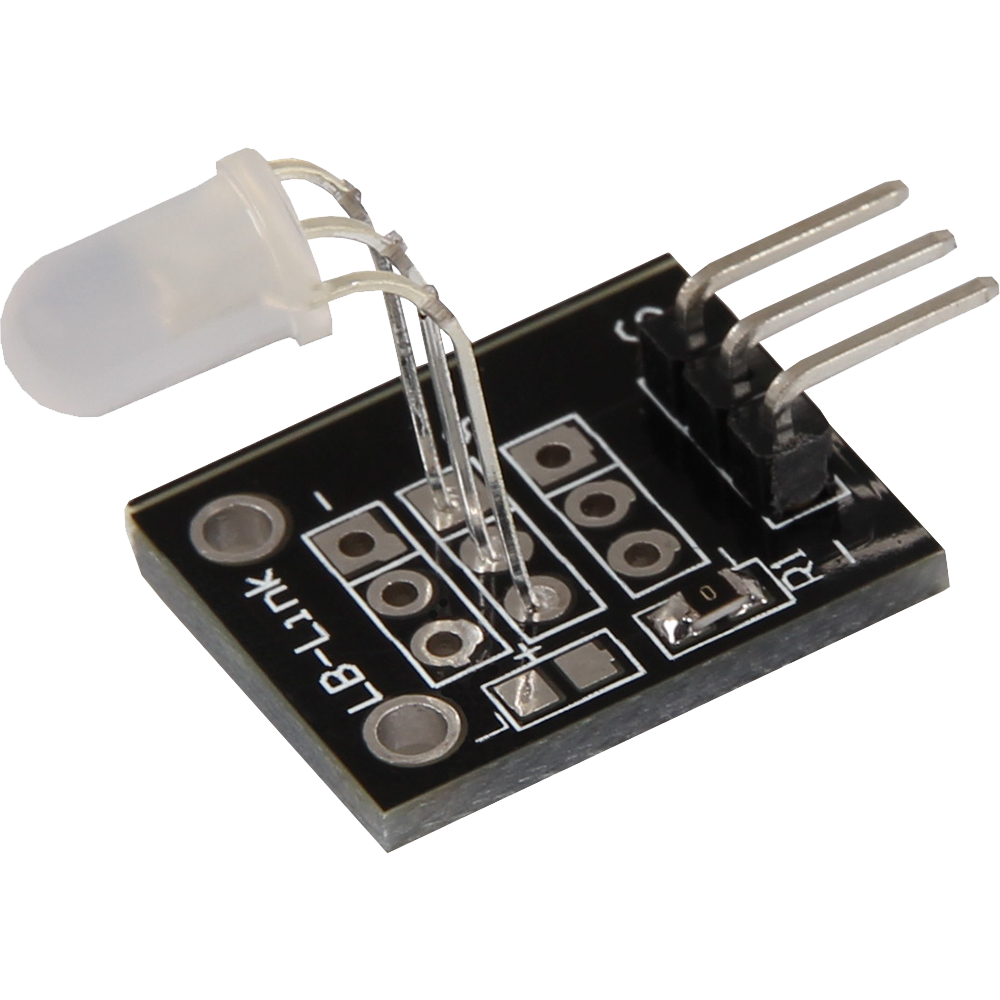
KY-011 2-Color 5mm LED
LED module which contains a red and green LED. These are connected to each other by means of a common cathode.
- Arduino
- Raspberry Pi
- Raspberry Pi Pico
- Micro:Bit
This LED module contains two LEDs in the colors red and green, which are connected to each other via a common cathode. This means that both LEDs share the same negative connection, which simplifies the circuit. The LEDs require a forward voltage between 2.0 V and 2.5 V and operate at a current of 20 mA.
This module is ideal for applications where colored signals or status indicators are required. By combining red and green, you can display different states or information by illuminating either one of the two colors or both at the same time.
The module is ideal for projects where visual feedback is important, such as in control and monitoring systems where the display of operating states or warning signals is required. Its compact size and easy integration make it a practical and versatile component for a wide range of applications.
| Technical Data | |
|---|---|
| Forward voltage | 2.0 V - 2.5 V |
| Forward current | 20 mA |
Series resistors:
Depending on the input voltage, series resistors are required.
| Input voltage | Series resistor |
|---|---|
| 3.3 V | 120 Ω |
| 5 V | 220 Ω |
Pin assignment


| Arduino | Sensor |
|---|---|
| Pin 9 | LED GREEN |
| Pin 10 | LED RED |
| GND | GND |
1. Code example: ON/OFF
This code example shows how the integrated LEDs can be changed alternately, every 3 seconds, by means of a definable output pin.
To load the following code example onto your Arduino, we recommend using the Arduino IDE. In the IDE, you can select the appropriate port and board for your device.
Copy the code below into your IDE. To upload the code to your Arduino, simply click on the upload button.
int led_red = 10; // Pin for red
int led_green = 9; // Pin for green

void setup() {
  // Initialization of output pins for the LEDs
  pinMode(led_red, OUTPUT);
  pinMode(led_green, OUTPUT);
}
// Main program loop
void loop() {
  digitalWrite(led_red, HIGH); // Red LED is switched on
  digitalWrite(led_green, LOW); // green LED is switched off
  delay(3000); // Wait for 3 seconds

  digitalWrite(led_red, LOW); // Red LED is switched off
  digitalWrite(led_green, HIGH); // green LED is switched on
  delay(3000); // Wait for a further 3 seconds in which the LEDs are then switched over
}
2. Code example: PWM
Pulse width modulation [PWM] can be used to regulate the brightness of an LED - in this process, the LED is switched on and off at specific time intervals, with the ratio of the switch-on and switch-off times corresponding to a relative brightness. Due to the inertia of human vision, human eyes interpret such on/off behavior as a change in brightness. More information on this topic can be found in this article by Analog IC Tips.
Several LEDs are integrated in this module - different colors can thus be created by superimposing different brightness levels. This is shown in the following code example.
To load the following code example onto your Arduino, we recommend using the Arduino IDE. In the IDE, you can select the appropriate port and board for your device.
Copy the code below into your IDE. To upload the code to your Arduino, simply click on the upload button.
int led_red = 10; // Pin for red
int led_green = 9; // Pin for green

void setup() {
  // Initialization of output pins for the LEDs
  pinMode(led_red, OUTPUT);
  pinMode(led_green, OUTPUT);
}
void loop() {
   // Within a For loop, the two LEDs are given different PWM values
   // This creates a color gradient in which different colors are created by mixing different
   // brightness levels of the two integrated LEDs, different colors are created
   for(int i = 255; i > 0; i--) {
      analogWrite(led_green, i);
      analogWrite(led_red, 255 - i);
      delay(15);
   }
   // In the second For loop, the color gradient is run backwards
   for(int i = 0; i <255; i++) {
      analogWrite(led_green, i);
      analogWrite(led_red, 255 - i);
      delay(15);
   }
}
This LED module contains two LEDs in the colors red and green, which are connected to each other via a common cathode. This means that both LEDs share the same negative connection, which simplifies the circuit. The LEDs require a forward voltage between 2.0 V and 2.5 V and operate at a current of 20 mA.
This module is ideal for applications where colored signals or status indicators are required. By combining red and green, you can display different states or information by illuminating either one of the two colors or both at the same time.
The module is ideal for projects where visual feedback is important, such as in control and monitoring systems where the display of operating states or warning signals is required. Its compact size and easy integration make it a practical and versatile component for a wide range of applications.
| Technical Data | |
|---|---|
| Forward voltage | 2.0 V - 2.5 V |
| Forward current | 20 mA |
Series resistors:
Depending on the input voltage, series resistors are required.
| Input voltage | Series resistor |
|---|---|
| 3.3 V [Red] | 120 Ω |
| 3,3 V [Green] | 120 Ω |
| 5 V [Red] | 220 Ω |
| 5 V [Green] | 220 Ω |
Pin assignment

| Raspberry Pi | Sensor |
|---|---|
| GPIO 23 [Pin 16] | LED GREEN |
| GPIO 24 [Pin 18] | LED RED |
| GND [Pin 6] | GND |
Code example (ON/OFF)
This code example shows how the integrated LEDs can be changed alternately, every 3 seconds, by means of a definable output pin.
from gpiozero import LED
import time

# LEDs are initialized on their corresponding GPIO pins
led_red = LED(24)
led_green = LED(23)

print("LED test [press CTRL+C to end the test]")

# Main program loop
try:
    while True:
        print("LED RED on for 3 seconds")
        led_red.on()
        led_green.off()
        time.sleep(3)  # Wait mode for 3 seconds

        print("LED GREEN on for 3 seconds")
        led_red.off()
        led_green.on()
        time.sleep(3)  # Wait mode for 3 seconds

# Clean up after the program has been completed
except KeyboardInterrupt:
    print("Program was terminated by the user")
Code example (PWM)
Pulse width modulation [PWM] can be used to regulate the brightness of an LED - in this process, the LED is switched on and off at specific time intervals, with the ratio of the switch-on and switch-off times corresponding to a relative brightness. Due to the inertia of human vision, human eyes interpret such on/off behavior as a change in brightness. More information on this topic can be found in this article by Analog IC Tips.
Several LEDs are integrated in this module - different colors can thus be created by superimposing different brightness levels. This is shown in the following code example.
from gpiozero import PWMLED
import time

# PWMLED instances for each LED
led_red = PWMLED(24)
led_green = PWMLED(23)

# This function generates the actual color
# The color intensity can be changed using the respective color variable
# After the color has been set, "time.sleep" is used to define the time for which the color in question is to be displayed
def led_farbe(red, green, pause):
    led_red.value = red
    led_green.value = green
    time.sleep(pause)

    # Switch off LEDs after the pause
    led_red.value = 0
    led_green.value = 0

print("LED test [press CTRL+C to end the test]")

# Main program loop:
# This has the task of creating a separate variable for each individual color and using a For loop to run through the color intensity of each individual color from 0-100%
# A color gradient is created by mixing the different brightness levels of the respective colors
try:
    while True:
        for x in range(0, 2):
            for y in range(0, 2):
                print(x, y)
                for i in range(0, 101):
                    # Scaling the intensity values from 0 to 1 for PWMLED
                    led_farbe(x * i / 100, y * i / 100, 0.02)

# Clean up after the program has been completed
except KeyboardInterrupt:
    print("Program was terminated by the user")
This LED module contains two LEDs in the colors red and green, which are connected to each other via a common cathode. This means that both LEDs share the same negative connection, which simplifies the circuit. The LEDs require a forward voltage between 2.0 V and 2.5 V and operate at a current of 20 mA.
This module is ideal for applications where colored signals or status indicators are required. By combining red and green, you can display different states or information by illuminating either one of the two colors or both at the same time.
The module is ideal for projects where visual feedback is important, such as in control and monitoring systems where the display of operating states or warning signals is required. Its compact size and easy integration make it a practical and versatile component for a wide range of applications.
| Technical Data | |
|---|---|
| Forward voltage | 2.0 V - 2.5 V |
| Forward current | 20 mA |
Series resistors:
Depending on the input voltage, series resistors are required.
| Input voltage | Series resistor |
|---|---|
| 3.3 V [Red] | 120 Ω |
| 3,3 V [Green] | 120 Ω |
| 5 V [Red] | 220 Ω |
| 5 V [Green] | 220 Ω |
Pin assignment

| Micro:Bit | Sensor |
|---|---|
| Pin 1 | LED GREEN |
| Pin 2 | LED RED |
| GND | GND |
This example turns on the LEDs depending on which button is pressed.
		input.onButtonPressed(Button.A, function () {
		    pins.digitalWritePin(DigitalPin.P2, 1)
		    pins.digitalWritePin(DigitalPin.P1, 0)
		})
		input.onButtonPressed(Button.B, function () {
		    pins.digitalWritePin(DigitalPin.P1, 1)
		    pins.digitalWritePin(DigitalPin.P2, 0)
		})
Sample program download
This LED module contains two LEDs in the colors red and green, which are connected to each other via a common cathode. This means that both LEDs share the same negative connection, which simplifies the circuit. The LEDs require a forward voltage between 2.0 V and 2.5 V and operate at a current of 20 mA.
This module is ideal for applications where colored signals or status indicators are required. By combining red and green, you can display different states or information by illuminating either one of the two colors or both at the same time.
The module is ideal for projects where visual feedback is important, such as in control and monitoring systems where the display of operating states or warning signals is required. Its compact size and easy integration make it a practical and versatile component for a wide range of applications.
| Technical Data | |
|---|---|
| Forward voltage | 2.0 V - 2.5 V |
| Forward current | 20 mA |
Series resistors:
Depending on the input voltage, series resistors are required.
| Input voltage | Series resistor |
|---|---|
| 3.3 V | 120 Ω |
| 5 V | 220 Ω |
Pin assignment

| Raspberry Pi Pico | Sensor |
|---|---|
| GPIO28 | LED RED |
| GPIO27 | LED GREEN |
| GND | GND |
1. Code example: ON/OFF
This code example shows how the integrated LEDs can be changed alternately, every 3 seconds, by means of a definable output pin.
To load the following code example onto your Pico, we recommend using the Thonny IDE. All you have to do first is go to Run > Configure interpreter ... > Interpreter > Which kind of interpreter should Thonny use for running your code? and select MicroPython (Raspberry Pi Pico).
Now copy the code below into your IDE and click on Run.
# Load libraries
from machine import Pin, PWM
from time import sleep

# Initialization of GPIO27 and GPIO28 as output
Red = Pin(28, Pin.OUT)
Green = Pin(27, Pin.OUT)

while True:
    # green light
    Green.value(1)
    Red.value(0)
    sleep(3)
    # red light
    Green.value(0)
    Red.value(1)
    sleep(3)
    # Deactivate LED
    Green.value(0)
    Red.value(0)
    sleep(3)
    # Activate both LEDs
    Green.value(1)
    Red.value(1)
    sleep(3)
    # Deactivate LED
    Green.value(0)
    Red.value(0)
    sleep(3)
2. Code example: PWM
By means of pulse width modulation [PWM], the brightness of an LED can be regulated - in this process, the LED is switched on and off at specific time intervals, with the ratio of the switch-on and switch-off time corresponding to a relative brightness. Due to the inertia of human vision, human eyes interpret such on/off behavior as a change in brightness. More information on this topic can be found in this article from mikrokontroller.net.
Several LEDs are integrated in this module - different colors can thus be created by superimposing different brightness levels. This is shown in the following code example.
To load the following code example onto your Pico, we recommend using the Thonny IDE. All you have to do first is go to Run > Configure interpreter ... > Interpreter > Which kind of interpreter should Thonny use for running your code? and select MicroPython (Raspberry Pi Pico).
Now copy the code below into your IDE and click on Run.
# Load libraries
import machine
import math

# Initialization of GPIO27 and GPIO28 as PWM pin
ledGreen = machine.PWM(machine.Pin(27))
ledGreen.freq(1000)
ledRed = machine.PWM(machine.Pin(28))
ledRed.freq(1000)

# Definition of a 2 digit list
RBG = [0,0]

# Function: Color space calculation for red and green
# Green is 90° offset to red
def sinColour(number):
    a = (math.sin(math.radians(number))+1)*32768
    c = (math.sin(math.radians(number+90))+1)*32768
    RBG = (int(a),int(c))
    return RBG

# Infinite loop where the color value for all two colors is shifted by 0.01 again and again
a = 0

while True:
    RBG = sinColour(a)
    a = a + 0.01
    if a == 360:
        a = 0
    ledRed.duty_u16(RBG[0])
    ledGreen.duty_u16(RBG[1])