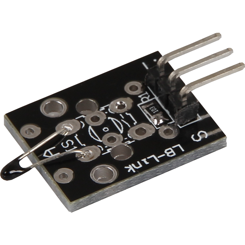
KY-013 Temperature sensor (NTC)
This module contains a NTC thermistor which can measure temperatures in the range of -55°C up to +125°C.
- Arduino
- Raspberry Pi
- Raspberry Pi Pico
- Micro:Bit
This module contains an NTC thermistor that can measure temperatures in the range from -55°C to +125°C. An NTC thermistor (Negative Temperature Coefficient) has the property that its resistance decreases as the temperature increases. This change in the resistance value makes it possible to calculate the corresponding temperature.
The relationship between temperature and resistance is not linear, but can be approximated mathematically. The change in resistance can be determined by using a voltage divider. A voltage divider consists of a known fixed resistance and the variable resistance of the thermistor. When a voltage is applied to the voltage divider, the voltage is divided according to the resistance values. By measuring the voltage across the thermistor, the current resistance can be calculated.
These resistance values can then be converted into temperatures. The exact calculation method and the mathematical approach for determining the temperature are described in the enclosed code examples. This module is ideal for applications where precise temperature measurements are required, such as in climate controls, monitoring systems and other temperature-dependent processes. Due to its high accuracy and wide measuring range, it offers a reliable solution for many temperature measurement tasks.


| Technical Data | |
|---|---|
| Operating voltage | 3,3 V - 5 V |
| Measuring range | -55 °C to +125 °C |
| Measurement accuracy | ± 0,5 °C |
| Known resistance | 10 kΩ |
| Specific resistance of the NTC | 3950 Ω |
Pin assignment


| Arduino | Sensor |
|---|---|
| A1 | Signal |
| 5 V | +V |
| GND | GND |
You can also use an ADC such as the KY-053. This ADC has a higher resolution than the internal ADC of the Arduino, which means that the sensor can be analysed more accurately.
Example code
The program measures the current voltage value at the NTC, calculates the temperature and translates the result to °C for serial output.
To load the following code example onto your Arduino, we recommend using the Arduino IDE. In the IDE, you can select the appropriate port and board for your device.
Copy the code below into your IDE. To upload the code to your Arduino, simply click on the upload button.
int ntc = A1; // Declaration of the sensor input pin
// Declaration of temporary variables
double raw_value;
double voltage;
double temperature;

void setup () {
  pinMode(ntc, INPUT); // Initialization sensor pin
  Serial.begin(9600); // Initialization of the serial monitor
  Serial.println("KY-013 NTC temperature test");
}

void loop () {
  // Read out analog value
  raw_value = analogRead(ntc);
  // Read out the voltage using an analog value
  voltage = raw_value * 5.0 / 1023.0;
  // Calculation of the temperature using the voltage
  temperature = ((voltage / 5.0) * 10000.0) / (1.0 - (voltage / 5.0));
  temperature = 1.0 / ((1.0 / 298.15) + (1.0 / 3950.0) * log(temperature / 10000.0));
  temperature = temperature - 273.15;
  // Output of the measured value
  Serial.println("Temperature: " + String(temperature) + " °C");
  delay(1000); // Wait 1 second for next measurement
}
This module contains an NTC thermistor that can measure temperatures in the range from -55°C to +125°C. An NTC thermistor (Negative Temperature Coefficient) has the property that its resistance decreases as the temperature increases. This change in the resistance value makes it possible to calculate the corresponding temperature.
The relationship between temperature and resistance is not linear, but can be approximated mathematically. The change in resistance can be determined by using a voltage divider. A voltage divider consists of a known fixed resistance and the variable resistance of the thermistor. When a voltage is applied to the voltage divider, the voltage is divided according to the resistance values. By measuring the voltage across the thermistor, the current resistance can be calculated.
These resistance values can then be converted into temperatures. The exact calculation method and the mathematical approach for determining the temperature are described in the enclosed code examples. This module is ideal for applications where precise temperature measurements are required, such as in climate controls, monitoring systems and other temperature-dependent processes. Due to its high accuracy and wide measuring range, it offers a reliable solution for many temperature measurement tasks.
| Technical Data | |
|---|---|
| Operating voltage | 3,3 V - 5 V |
| Measuring range | -55 °C to +125 °C |
| Measurement accuracy | ± 0,5 °C |
| Known resistance | 10 kΩ |
| Specific resistance of the NTC | 3950 Ω |
Pin assignment

| Raspberry Pi | Sensor |
|---|---|
| - | Signal |
| 3,3 V [Pin 1] | +V |
| GND [Pin 6] | GND |
| Sensor | KY-053 |
|---|---|
| Signal | A0 |
| +V | - |
| GND | - |
| Raspberry Pi | KY-053 |
|---|---|
| GPIO 3 [Pin 5] | SCL |
| Gpio 2 [Pin 3] | SDA |
| 3,3 V [Pin 1] | VDD |
| GND [Pin 6] | GND |
Analog sensor, therefore the following must be considered: The Raspberry Pi has, in contrast to the Arduino, no analog inputs or there is no ADC (analog digital converter) integrated in the chip of the Raspberry Pi. This limits the Raspberry Pi, if you want to use sensors, which do not output digital values, but a continuously changing value (example: potentiometer -> different position = different voltage value).
To avoid this problem, our sensor kit X40 contains the KY-053, a module with a 16-bit ADC, which you can use on the Raspberry to expand it with 4 analog inputs. This module is connected to the Raspberry Pi via I2C, takes over the analog measurement and transfers the value digitally to the Raspberry Pi.
Thus we recommend to connect the KY-053 module with the said ADC in between for analog sensors of this set. More information can be found on the KY-053 Analog Digital Converter information page.
Example code
The program uses the corresponding ADS1x15 and I2C Python libraries from Adafruit to drive the ADS1115 ADC. These have been published at the following link https://github.com/adafruit/Adafruit_CircuitPython_ADS1x15 under the MIT license. The required libraries are not included in the download package below.
Please note that you need to enable I2C on your Raspberry Pi before using this example.
import time
import board
import busio
import adafruit_ads1x15.ads1115 as ADS
from adafruit_ads1x15.analog_in import AnalogIn
import math

# Create the I2C bus
i2c = busio.I2C(board.SCL, board.SDA)

# Create the ADC object with the I2C bus
ads = ADS.ADS1115(i2c)

# Define maximum possible voltage (depending on your reference voltage)
voltageMax = 3.3

# Create individual inputs on channels
chan0 = AnalogIn(ads, ADS.P0)
chan1 = AnalogIn(ads, ADS.P1)
chan2 = AnalogIn(ads, ADS.P2)
chan3 = AnalogIn(ads, ADS.P3)

# Main program loop
while True:
    # Calculation of the temperature via an NTC resistor
    ntc_resistance = ((chan0.voltage / voltageMax) * 10000) / (1 - (chan0.voltage / voltageMax))
    temperatur = 1 / ((1 / 298.15) + (1 / 3950) * math.log(ntc_resistance / 10000))
    temperatur -= 273.15  # Conversion from Kelvin to Celsius
    print("Temperatur: {:.2f} °C".format(temperatur))
    print("---------------------------------------------------")
    time.sleep(1)
This module contains an NTC thermistor that can measure temperatures in the range from -55°C to +125°C. An NTC thermistor (Negative Temperature Coefficient) has the property that its resistance decreases as the temperature increases. This change in the resistance value makes it possible to calculate the corresponding temperature.
The relationship between temperature and resistance is not linear, but can be approximated mathematically. The change in resistance can be determined by using a voltage divider. A voltage divider consists of a known fixed resistance and the variable resistance of the thermistor. When a voltage is applied to the voltage divider, the voltage is divided according to the resistance values. By measuring the voltage across the thermistor, the current resistance can be calculated.
These resistance values can then be converted into temperatures. The exact calculation method and the mathematical approach for determining the temperature are described in the enclosed code examples. This module is ideal for applications where precise temperature measurements are required, such as in climate controls, monitoring systems and other temperature-dependent processes. Due to its high accuracy and wide measuring range, it offers a reliable solution for many temperature measurement tasks.
| Technical Data | |
|---|---|
| Operating voltage | 3,3 V - 5 V |
| Measuring range | -55 °C to +125 °C |
| Measurement accuracy | ± 0,5 °C |
| Known resistance | 10 kΩ |
| Specific resistance of the NTC | 3950 Ω |
Pin assignment

| Micro:Bit | Sensor |
|---|---|
| - | Signal |
| 3 V | +V |
| GND | GND |
| Sensor | KY-053 |
|---|---|
| Signal | A0 |
| +V | - |
| GND | - |
| Micro:Bit | KY-053 |
|---|---|
| Pin 19 | SCL |
| Pin 20 | SDA |
| 3 V | VDD |
| GND | GND |
Analog sensor, therefore the following must be observed: The Micro:Bit has analog inputs or there is an ADC (analog digital converter) integrated in the chip of the Micro:Bit. However, these are only limited to 10-bit and therefore offer only a rather low accuracy for analog measurements.
To avoid this problem, our sensor kit X40 contains the KY-053, a module with a 16-bit ADC, which you can use on the Micro:Bit to expand it by 4 analog inputs. This is connected to the Micro:Bit via I2C, takes over the analog measurement and transfers the value digitally to the Micro:Bit.
Therefore we recommend to connect the KY-053 module with the mentioned ADC in between for analog sensors of this set. More information can be found on the KY-053 Analog Digital Converter information page KY-053 Analog Digital Converter.
Example code
The program uses the corresponding library from us to control the ADS1115 ADC. This has been published under the following link pxt-ads1115 under the MIT-License.
		let _2 = 0
		let temperature = 0
		ADS1115.setMode(mode.Multi)
		ADS1115.setRate(rate.Rate6)
		ADS1115.setGain(gain.One)
		ADS1115.initADS1115(userInI2C.Gnd)
		basic.forever(function () {
		    _2 = ADS1115.raw_to_v(ADS1115.read(0))
		    temperature = _2 / 3.3 * 10000 / (1 - _2 / 3.3)
		    temperature = 1 / (1 / 298.15 + 1 / 3950 * Math.log(temperature / 10000))
		    temperature = temperature - 273.15
		    serial.writeLine("" + (temperature))
		    basic.pause(1000)
		})
Sample program download
This module contains an NTC thermistor that can measure temperatures in the range from -55°C to +125°C. An NTC thermistor (Negative Temperature Coefficient) has the property that its resistance decreases as the temperature increases. This change in the resistance value makes it possible to calculate the corresponding temperature.
The relationship between temperature and resistance is not linear, but can be approximated mathematically. The change in resistance can be determined by using a voltage divider. A voltage divider consists of a known fixed resistance and the variable resistance of the thermistor. When a voltage is applied to the voltage divider, the voltage is divided according to the resistance values. By measuring the voltage across the thermistor, the current resistance can be calculated.
These resistance values can then be converted into temperatures. The exact calculation method and the mathematical approach for determining the temperature are described in the enclosed code examples. This module is ideal for applications where precise temperature measurements are required, such as in climate controls, monitoring systems and other temperature-dependent processes. Due to its high accuracy and wide measuring range, it offers a reliable solution for many temperature measurement tasks.
| Technical Data | |
|---|---|
| Operating voltage | 3,3 V - 5 V |
| Measuring range | -55 °C to +125 °C |
| Measurement accuracy | ± 0,5 °C |
| Known resistance | 10 kΩ |
| Specific resistance of the NTC | 3950 Ω |
Pin assignment

| Raspberry Pi Pico | Sensor |
|---|---|
| 3,3 V | +V |
| GND | GND |
| GPIO26 (A0) | Signal |
You can also use an ADC such as the KY-053. This ADC has a higher resolution than the internal ADC of the Raspberry Pi Pico, which means that the sensor can be analysed more accurately.
Example code
The program measures the current voltage value on the NTC, calculates the temperature and translates the result into °C for the serial output.
To load the following code example onto your Pico, we recommend using the Thonny IDE. All you have to do first is go to Run > Configure interpreter ... > Interpreter > Which kind of interpreter should Thonny use for running your code? and select MicroPython (Raspberry Pi Pico).
Now copy the code below into your IDE and click on Run.
# Load libraries
from machine import ADC
import math
from time import sleep

# Initialization of the ADC0 (GPIO26)
adc = ADC(0)

print("KY-013 Temperature measurement")

while True:
    # Read ADC0 as a decimal number
    read = adc.read_u16()
    # Calculate voltage
    voltage = read * 3.3 / 65536
    # Conversion from voltage to temperature
    temperature = ((voltage / 3.3) * 10000) / (1 - (voltage / 3.3))
    temperature = 1 / ((1 / 298.15) + (1 / 3950) * math.log(temperature / 10000))
    temperature = temperature - 273.15
    # Serial output of the calculated temperature
    print("Temperature: " + str(temperature) + " °C")
    sleep(1)