KY-032 Obstacle detector
This sensor uses infrared light to detect obstacles. If the emitted infrared light hits an obstacle, it is reflected and detected by the photodiode.
- Arduino
- Raspberry Pi
- Raspberry Pi Pico
- Micro:Bit
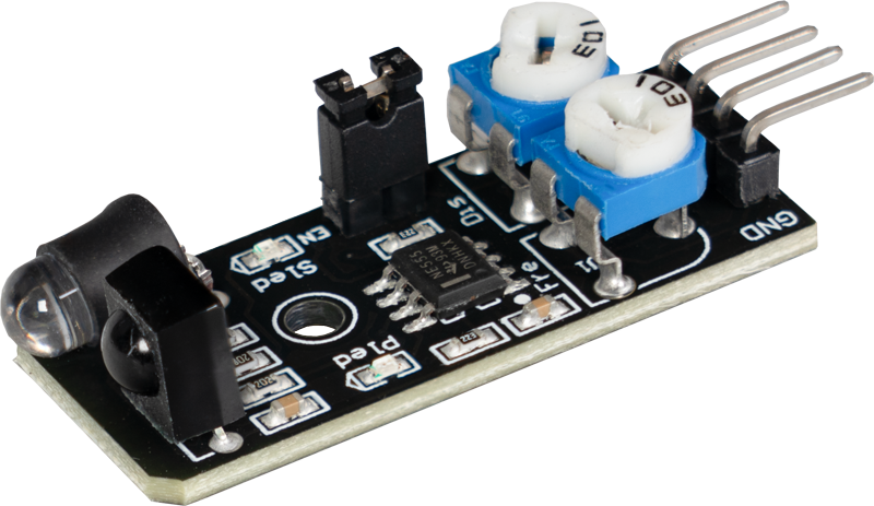
This obstacle detector uses infrared light to detect obstacles. When the emitted infrared light hits an obstacle, it is reflected and detected by a photodiode. The distance at which obstacles are detected can be set using two controllers. This module is particularly useful in control systems such as those used in robots to stop autonomously in front of obstacles. It enables reliable and precise detection of objects, allowing robots to navigate safely and avoid collisions. The easy adjustment of sensitivity makes the sensor versatile for various applications where obstacle detection is important.
State 1: There is no obstacle in front of the detector [LED on the module: Off] [Sensor Signal= Digital On]
State 2: Detector has detected obstacle [LED on module: On] [Sensor Signal= Digital Off]
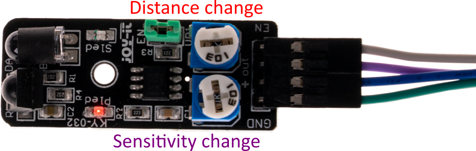
This sensor also has an enable line. This line can be used to activate or deactivate the detection of the sensor. In the delivery state of the sensor, however, the enable line is deactivated and the sensor is therefore permanently active. If the functionality of the enable line is desired, the jumper EN (green in the picture) must be removed and a corresponding control signal must be applied to the enable pin.
Please note: The sensor is additionally equipped with two adjustable controllers. Via these the measurable distance as well as the sensitivity of the sensor can be adjusted.
Pin assignment


| Arduino | Sensor |
|---|---|
| - | Enable |
| 5 V | +V |
| GND | GND |
| Pin 10 | Signal |
Code example
The program reads the current state of the sensor pins and displays in the serial console whether the obstacle detector is currently in front of an obstacle or not.
To load the following code example onto your Arduino, we recommend using the Arduino IDE. In the IDE, you can select the appropriate port and board for your device.
Copy the code below into your IDE. To upload the code to your Arduino, simply click on the upload button.
int obstacle_detector = 10; // Declaration of the sensor input pin
int value; // Temporary variable

void setup () {
  pinMode(obstacle_detector, INPUT); // Initialization sensor pin
  digitalWrite(obstacle_detector, HIGH); // Activation of internal pull-up resistor
  Serial.begin(9600); // Initialization of the serial monitor
  Serial.println("KY-032 Obstacle detection");
}

void loop () {
  // The current signal at the sensor is read out.
  value = digitalRead(obstacle_detector);
  // If a signal could be detected, this is displayed on the serial monitor.
  if (value == LOW) {
    Serial.println("Obstacle recognized");
    delay(200); // 200 ms break
  }
}
This obstacle detector uses infrared light to detect obstacles. When the emitted infrared light hits an obstacle, it is reflected and detected by a photodiode. The distance at which obstacles are detected can be set using two controllers. This module is particularly useful in control systems such as those used in robots to stop autonomously in front of obstacles. It enables reliable and precise detection of objects, allowing robots to navigate safely and avoid collisions. The easy adjustment of sensitivity makes the sensor versatile for various applications where obstacle detection is important.
State 1: There is no obstacle in front of the detector [LED on the module: Off] [Sensor Signal= Digital On]
State 2: Detector has detected obstacle [LED on module: On] [Sensor Signal= Digital Off]
This sensor also has an enable line. This line can be used to activate or deactivate the detection of the sensor. In the delivery state of the sensor, however, the enable line is deactivated and the sensor is therefore permanently active. If the functionality of the enable line is desired, the jumper EN (green in the picture) must be removed and a corresponding control signal must be applied to the enable pin.
Please note: The sensor is additionally equipped with two adjustable controllers. Via these the measurable distance as well as the sensitivity of the sensor can be adjusted.
Pin assignment

| Raspberry Pi | Sensor |
|---|---|
| - | Enable |
| 3,3 V [Pin 1] | +V |
| GND [Pin 6] | GND |
| GPIO 24 [Pin 18] | Signal |
Code example
The program reads the current status of the sensor pin and outputs in the serial console whether the obstacle detector is currently in front of an obstacle or not.
from gpiozero import DigitalInputDevice
import time

# Initialize the input pin to which the sensor is connected
sensor = DigitalInputDevice(24, pull_up=True)  # pull_up=True activates the internal pull-up resistor

# Pause between the output of the result is defined (in seconds)
delayTime = 0.5

print("Sensor test [press CTRL+C to end the test]")

# Hauptprogrammschleife
try:
    while True:
        if sensor.value:  # True if the pin is HIGH (no obstacle)
            print("Obstacle recognized")
        else:  # False if the pin is LOW (obstacle detected)
            print("No obstacle")
        print("---------------------------------------")

        # Reset + Delay
        time.sleep(delayTime)

# Clean up after the program has been completed
except KeyboardInterrupt:
    print("Program was interrupted by user")
This obstacle detector uses infrared light to detect obstacles. When the emitted infrared light hits an obstacle, it is reflected and detected by a photodiode. The distance at which obstacles are detected can be set using two controllers. This module is particularly useful in control systems such as those used in robots to stop autonomously in front of obstacles. It enables reliable and precise detection of objects, allowing robots to navigate safely and avoid collisions. The easy adjustment of sensitivity makes the sensor versatile for various applications where obstacle detection is important.
State 1: There is no obstacle in front of the detector [LED on the module: Off] [Sensor Signal= Digital On]
State 2: Detector has detected obstacle [LED on module: On] [Sensor Signal= Digital Off]
This sensor also has an enable line. This line can be used to activate or deactivate the detection of the sensor. In the delivery state of the sensor, however, the enable line is deactivated and the sensor is therefore permanently active. If the functionality of the enable line is desired, the jumper EN (green in the picture) must be removed and a corresponding control signal must be applied to the enable pin.
Please note: The sensor is additionally equipped with two adjustable controllers. Via these the measurable distance as well as the sensitivity of the sensor can be adjusted.
Pin assignment

| Micro: Bit | Sensor |
|---|---|
| Pin 1 | Signal |
| 3 V | +V |
| GND | GND |
Code example
This is a sample program that outputs text serially when a signal is detected at the sensor.
		pins.setPull(DigitalPin.P1, PinPullMode.PullUp)
		basic.forever(function () {
		    if (pins.digitalReadPin(DigitalPin.P1) == 1) {
		        serial.writeLine("No obstacle")
		        basic.pause(100)
		    } else {
		        serial.writeLine("Obstacle detected")
		        basic.pause(100)
		    }
		})
Sample program download
This obstacle detector uses infrared light to detect obstacles. When the emitted infrared light hits an obstacle, it is reflected and detected by a photodiode. The distance at which obstacles are detected can be set using two controllers. This module is particularly useful in control systems such as those used in robots to stop autonomously in front of obstacles. It enables reliable and precise detection of objects, allowing robots to navigate safely and avoid collisions. The easy adjustment of sensitivity makes the sensor versatile for various applications where obstacle detection is important.
State 1: There is no obstacle in front of the detector [LED on the module: Off] [Sensor Signal= Digital On]
State 2: Detector has detected obstacle [LED on module: On] [Sensor Signal= Digital Off]
This sensor also has an enable line. This line can be used to activate or deactivate the detection of the sensor. In the delivery state of the sensor, however, the enable line is deactivated and the sensor is therefore permanently active. If the functionality of the enable line is desired, the jumper EN (green in the picture) must be removed and a corresponding control signal must be applied to the enable pin.
Please note: The sensor is additionally equipped with two adjustable controllers. Via these the measurable distance as well as the sensitivity of the sensor can be adjusted.
Pin assignment

| Raspberry Pi Pico | Sensor |
|---|---|
| - | Enable |
| 3.3V | +V |
| GND | GND |
| GPIO18 | Signal |
Code example
The program reads the current status of the sensor pin and outputs in the serial output whether the obstacle detector is currently in front of an obstacle.
To load the following code example onto your Pico, we recommend using the Thonny IDE. All you have to do first is go to Run > Configure interpreter ... > Interpreter > Which kind of interpreter should Thonny use for running your code? and select MicroPython (Raspberry Pi Pico).
Now copy the code below into your IDE and click on Run.
# Load libraries
from machine import Pin, Timer
from time import sleep

# Initialization of GPIO as input
sensor = Pin(18, Pin.IN, Pin.PULL_DOWN)

print("KY-032 Obstacle detection")

# Continuous loop for continuous serial output
while True:
    if sensor.value() == 0:
        print("Obstacle recognized")
    else:
        print("No obstacle recognized")

    print("------------------------------------------------------")
    sleep(0.5)