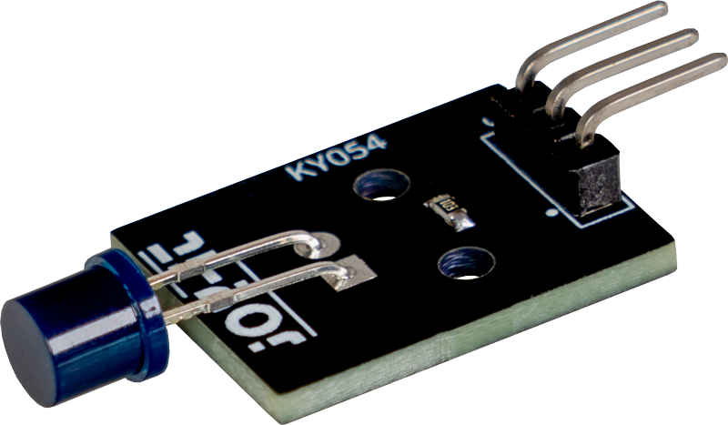
KY-054 Phototransistor
This phototransistor is a component that detects light and converts it into an electrical signal, similar to a switch that is controlled by light.
- Arduino
- Raspberry Pi
- Raspberry Pi Pico
- Micro:Bit
The sensor can be used to determine how bright the surroundings are, which was previously used in light meters for cameras, for example. Phototransistors are often used to adjust the brightness of a display (for example in an alarm clock or the dashboard of a car) to match the ambient light intensity: When it is dark, the display should only glow dimly so as not to dazzle.
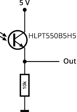
A light sensor changes its electrical value depending on the intensity of the ambient light. Until about 10 years ago, photoresistors were often used for this purpose, which are called Light Dependent Resistors (LDR). The more light falls on the photoresistor, the lower its resistance becomes. However, these are being used less and less for environmental reasons, as the materials used are banned in the directives. Nowadays, the use of phototransistors is up to date. The luminous flux incident on the surface replaces the usual base connection and, as usual, controls the collector-emitter current. The flowing current thus represents the brightness and can be mathematically converted into illuminance (in the case of linear types, as in this case) or using a comparison table. By coloring the transparent housing (usually dark blue), the phototransistor can be blocked for certain wavelengths so that it is primarily designed for infrared radiation, for example, and is less affected by artificial light. The phototransistor influences the flowing current depending on the incidence of light, so that the voltage dropping across the resistor changes (voltage divider) from which the light intensity can then be calculated.
Attention! This sensor is only included in revision 2 of the sensor kit and has replaced sensor KY-018!
| Technical data | |
|---|---|
| Operating voltage | 3,3 V - 5 V |
| Fixed, known resistance | 10 kΩ |
| Dimensions | 28 x 15 x 7 mm |
Pin assignment


| Arduino | Sensor |
|---|---|
| GND | GND |
| 5 V | +V |
| Pin A5 | Signal |
Code example
To load the following code example onto your Arduino, we recommend using the Arduino IDE. In the IDE, you can select the appropriate port and board for your device.
Copy the code below into your IDE. To upload the code to your Arduino, simply click on the upload button.
// Define pin for phototransistor
int light_sensor = A5;
// Definition of the parameters required for the calculation
const double U1 = 5.0;
const double R2 = 10000.0;
double U2;
double I;
double R1;
double lux;
int rawValue;

void setup() {
  // Define the pin mode
  pinMode(light_sensor, INPUT);
  // Set up serial communication for serial monitor
  Serial.begin(9600);
  Serial.println("KY-054 Brightness test");
}

void loop() {
  // Reading the voltage of the light sensor
  rawValue = analogRead(light_sensor);
  U2 = rawValue * (5.0/1023) ;

  // Check U2 for the division
  if (U2 != 0) {
    // Calculate the resistance of the sensor
    R1 = (U1 * R2) / U2;
    // Calculate current
    I = (U1 / R1) * 1000000.0;
    // Calculate lux
    lux = log(I)/0.06;
  }
  else lux = 0;

  // Output the result on the serial monitor
  Serial.print("Lux:\t");
  Serial.println(lux);

  // wait for one second
  delay(1000);
}
The sensor can be used to determine how bright the surroundings are, which was previously used in light meters for cameras, for example. Phototransistors are often used to adjust the brightness of a display (for example in an alarm clock or the dashboard of a car) to match the ambient light intensity: When it is dark, the display should only glow dimly so as not to dazzle.
A light sensor changes its electrical value depending on the intensity of the ambient light. Until about 10 years ago, photoresistors were often used for this purpose, which are called Light Dependent Resistors (LDR). The more light falls on the photoresistor, the lower its resistance becomes. However, these are being used less and less for environmental reasons, as the materials used are banned in the directives. Nowadays, the use of phototransistors is up to date. The luminous flux incident on the surface replaces the usual base connection and, as usual, controls the collector-emitter current. The flowing current thus represents the brightness and can be mathematically converted into illuminance (in the case of linear types, as in this case) or using a comparison table. By coloring the transparent housing (usually dark blue), the phototransistor can be blocked for certain wavelengths so that it is primarily designed for infrared radiation, for example, and is less affected by artificial light. The phototransistor influences the flowing current depending on the incidence of light, so that the voltage dropping across the resistor changes (voltage divider) from which the light intensity can then be calculated.
Attention! This sensor is only included in revision 2 of the sensor kit and has replaced sensor KY-018!
| Technical data | |
|---|---|
| Operating voltage | 3,3 V - 5 V |
| Fixed, known resistance | 10 kΩ |
| Dimensions | 28 x 15 x 7 mm |
Pin assignment

| Raspberry Pi | Sensor |
|---|---|
| - | Signal |
| 3,3 V [Pin 1] | +V |
| GND [Pin 6] | GND |
| Sensor | KY-053 |
|---|---|
| Signal | A0 |
| +V | - |
| GND | - |
| Raspberry Pi | KY-053 |
|---|---|
| 3,3 V [Pin 1] | +V |
| GND [Pin 6] | GND |
| GPIO 3 [Pin 5] | SCL |
| GPIO 2 [Pin 3] | SDA |
Analog sensor, therefore the following must be noted: Unlike the Arduino, the Raspberry Pi has no analog inputs or there is no ADC (analog digital converter) integrated in the Raspberry Pi's chip. This limits the Raspberry Pi if you want to use sensors that do not output digital values, but rather a continuously changing value (example: potentiometer -> different position = different voltage value).
To avoid this problem, our sensor kit X40 contains the KY-053, a module with a 16-bit ADC, which you can use on the Raspberry to expand it by 4 analog inputs. This is connected to the Raspberry Pi via I2C, takes over the analog measurement and transfers the value digitally to the Raspberry Pi.
We therefore recommend connecting the KY-053 module with the aforementioned ADC between the analog sensors in this set. Further information can be found on the information page for the KY-053 Analog Digital Converter.
Code example
Attention! To use this module in combination with the KY-053 Analog Digital Converter, a virtual environment must be set up. All the necessary information can be found here.
#!/usr/bin/python
# coding=utf-8
import time
import board
import busio
import adafruit_ads1x15.ads1115 as ADS
from adafruit_ads1x15.analog_in import AnalogIn
import gpiozero

# Creating the I2C bus
i2c = busio.I2C(board.SCL, board.SDA)

# Creating the ADC object via the I2C bus
ads = ADS.ADS1115(i2c)

# Create single-ended input on the channels
chan0 = AnalogIn(ads, ADS.P0)
chan1 = AnalogIn(ads, ADS.P1)
chan2 = AnalogIn(ads, ADS.P2)
chan3 = AnalogIn(ads, ADS.P3)

delayTime = 1

while True:
    analog = '%.2f' % chan0.voltage

    # Output via console
    print ("Analog voltage value:", analog,"V")
    time.sleep(delayTime)
The sensor can be used to determine how bright the surroundings are, which was previously used in light meters for cameras, for example. Phototransistors are often used to adjust the brightness of a display (for example in an alarm clock or the dashboard of a car) to match the ambient light intensity: When it is dark, the display should only glow dimly so as not to dazzle.
A light sensor changes its electrical value depending on the intensity of the ambient light. Until about 10 years ago, photoresistors were often used for this purpose, which are called Light Dependent Resistors (LDR). The more light falls on the photoresistor, the lower its resistance becomes. However, these are being used less and less for environmental reasons, as the materials used are banned in the directives. Nowadays, the use of phototransistors is up to date. The luminous flux incident on the surface replaces the usual base connection and, as usual, controls the collector-emitter current. The flowing current thus represents the brightness and can be mathematically converted into illuminance (in the case of linear types, as in this case) or using a comparison table. By coloring the transparent housing (usually dark blue), the phototransistor can be blocked for certain wavelengths so that it is primarily designed for infrared radiation, for example, and is less affected by artificial light. The phototransistor influences the flowing current depending on the incidence of light, so that the voltage dropping across the resistor changes (voltage divider) from which the light intensity can then be calculated.
Attention! This sensor is only included in revision 2 of the sensor kit and has replaced sensor KY-018!
| Technical data | |
|---|---|
| Operating voltage | 3,3 V - 5 V |
| Fixed, known resistance | 10 kΩ |
| Dimensions | 28 x 15 x 7 mm |
Pin assignment

| Micro:Bit | Sensor |
|---|---|
| GND | GND |
| 5 V | +V |
| Pin A5 | Signal |
Code example
Der Micro:Bit verfügt bereits über einen integrierten 10-Bit ADC. Werden weitere Kanäle oder eine höhere Genauigkeit benötigt, so kann der Micro:Bit mit Hilfe des KY-053 Analog Digital Converter Moduls um 4 ADC Kanäle mit 16-Bit Genauigkeit erweitert werden.
Zur Ansteuerung empfehlen wir die Verwendung der pxt-ads1115 Biblitohek, die von uns unter der MIT-Lizenz veröffentlicht wurde.
Die Bibliothek können Sie hinzufügen, indem Sie auf der Makecode Seite auf Erweiterungen klicken und dort dann ADS1115 in der Suchleiste eingeben. Nachdem Sie das getan haben, müssen Sie nur noch auf die Erweiterung klicken, um diese automatisch für ihr aktuelles Projekt hinzuzufügen.
		ADS1115.setMode(mode.Multi)
		ADS1115.setRate(rate.Rate5)
		ADS1115.setGain(gain.One)
		ADS1115.initADS1115(userInI2C.Gnd)
		basic.forever(function () {
		    serial.writeLine("" + (ADS1115.read(0)))
		    serial.writeLine("" + (ADS1115.raw_to_v(ADS1115.read(0))))
		    basic.pause(500)
		})
Download sample program
The sensor can be used to determine how bright the surroundings are, which was previously used in light meters for cameras, for example. Phototransistors are often used to adjust the brightness of a display (for example in an alarm clock or the dashboard of a car) to match the ambient light intensity: When it is dark, the display should only glow dimly so as not to dazzle.
A light sensor changes its electrical value depending on the intensity of the ambient light. Until about 10 years ago, photoresistors were often used for this purpose, which are called Light Dependent Resistors (LDR). The more light falls on the photoresistor, the lower its resistance becomes. However, these are being used less and less for environmental reasons, as the materials used are banned in the directives. Nowadays, the use of phototransistors is up to date. The luminous flux incident on the surface replaces the usual base connection and, as usual, controls the collector-emitter current. The flowing current thus represents the brightness and can be mathematically converted into illuminance (in the case of linear types, as in this case) or using a comparison table. By coloring the transparent housing (usually dark blue), the phototransistor can be blocked for certain wavelengths so that it is primarily designed for infrared radiation, for example, and is less affected by artificial light. The phototransistor influences the flowing current depending on the incidence of light, so that the voltage dropping across the resistor changes (voltage divider) from which the light intensity can then be calculated.
Attention! This sensor is only included in revision 2 of the sensor kit and has replaced sensor KY-018!
| Technical data | |
|---|---|
| Operating voltage | 3,3 V - 5 V |
| Fixed, known resistance | 10 kΩ |
| Dimensions | 28 x 15 x 7 mm |
Pin assignment

| Raspberry Pi Pico | Sensor |
|---|---|
| GND | GND |
| 5 V | +V |
| GPIO26 (A0) | Signal |
Code example
To load the following code example onto your Pico, we recommend using the Thonny IDE. All you have to do first is go to Run > Configure interpreter ... > Interpreter > Which kind of interpreter should Thonny use for running your code? and select MicroPython (Raspberry Pi Pico).
Now copy the code below into your IDE and click on Run.
# Load libraries
from machine import ADC
import math
from time import sleep

# Define fixed variables
U1 = 5
R2 = 10000

# Initialize sensor on GPIO26
sensor = ADC(0)

print("KY-054 Brightness test")

while True:
    # Read out the voltage of the light sensor
    rawValue = sensor.read_u16()
    U2 = rawValue * 3.3 / 65536

    # Check U2 for the division
    if U2 != 0:
        # Calculate the resistance of the sensor
        R1 = (U1 * R2) / U2
        # Calculate current
        I = (U1 / R1) * 1000000
        # Calculate lux
        lux = math.log(I) / 0.06
    else:
        lux = 0

    # Output result
    print("Lux:", round(lux, 2))

    sleep(1)