KY-023 Joystick (X-Y-Axis)
X and Y position of the joystick, are output as analog voltage on the output pins.
- Arduino
- Raspberry Pi
- Raspberry Pi Pico
- Micro:Bit
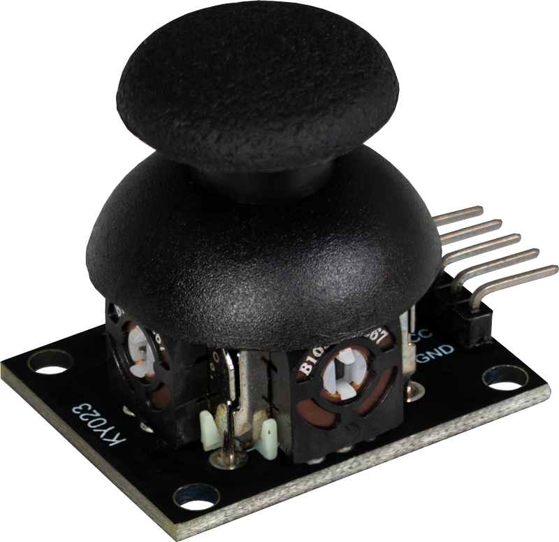
This module detects the X and Y position of a joystick and outputs this as an analog voltage at the output pins. A separate potentiometer is installed for each axis, X and Y. In the idle state, the potentiometer is in the middle, which means that the resistances and therefore the voltages are the same.
If the position of the X or Y axis is changed, the resistances change depending on the new position. This change in resistance leads to different voltage values that can be measured between the resistors. This allows the exact position of the axis to be determined.
This module is ideal for applications such as control systems in games, robotics or other projects where precise detection of movement is required. By outputting the position as an analog voltage, the joystick can be easily integrated into various electronic systems to provide accurate and intuitive control.

Pin assignment


| Arduino | Sensor |
|---|---|
| 5 V | +5V |
| GND | GND |
| Pin A1 | VRy |
| Pin A0 | VRx |
| Pin 3 | Button |
Code example
The program reads the current values of the input pins, converts them to a voltage (0-1023 -> 0 V-5 V) and outputs it in the serial output.
To load the following code example onto your Arduino, we recommend using the Arduino IDE. In the IDE, you can select the appropriate port and board for your device.
Copy the code below into your IDE. To upload the code to your Arduino, simply click on the upload button.
// Declaration and initialization of the input pins
int joystick_X = A0; // x-axis signal
int joystick_Y = A1; // y-axis signal
int joystick_button = 3; // button

void setup () {
  pinMode(joystick_X, INPUT);
  pinMode(joystick_Y, INPUT);
  pinMode(joystick_button, INPUT);
  // Since the button pulls the signal to ground when pressed,
  // we hereby activate the pull-up resistor
  digitalWrite(joystick_button, HIGH);
  Serial.begin (9600); // Serial output with 9600 bps
}

// The program reads the current values of the input pins
// and outputs them to the serial output
void loop () {
  // Temporary variables
  float temp_x, temp_y;
  int button_value;

  // Current values are read out, converted to the voltage value...
  temp_x = analogRead(joystick_X) * (5.0 / 1023.0);
  temp_y = analogRead(joystick_Y) * (5.0 / 1023.0);
  button_value = digitalRead(joystick_button);

  // ... and issued at this point
  Serial.print ("x-axis: ");
  Serial.print (temp_x, 4);
  Serial.print ("V, \ty-axis: ");
  Serial.print (temp_y, 4);
  Serial.print ("V, \tbutton: ");
  if (button_value == 1) {
      Serial.println("not pressed");
  }
  else {
      Serial.println("pressed");
  }
  delay(1000);
}
This module detects the X and Y position of a joystick and outputs this as an analog voltage at the output pins. A separate potentiometer is installed for each axis, X and Y. In the idle state, the potentiometer is in the middle, which means that the resistances and therefore the voltages are the same.
If the position of the X or Y axis is changed, the resistances change depending on the new position. This change in resistance leads to different voltage values that can be measured between the resistors. This allows the exact position of the axis to be determined.
This module is ideal for applications such as control systems in games, robotics or other projects where precise detection of movement is required. By outputting the position as an analog voltage, the joystick can be easily integrated into various electronic systems to provide accurate and intuitive control.
Pin assignment

| Raspberry Pi | Sensor |
|---|---|
| GPIO 24 [Pin 18] | Button |
| 3,3 V [Pin 1] | +5V |
| GND [Pin 6] | GND |
| - | VRy |
| - | VRx |
| Sensor | KY-053 |
|---|---|
| VRy | A1 |
| VRx | A0 |
| Raspberry Pi | KY-053 |
|---|---|
| GPIO 3 [Pin 5] | SCL |
| Gpio 2 [Pin 3] | SDA |
| 3,3 V [Pin 17] | VDD |
| GND [Pin 14] | GND |
Analog sensor, therefore the following must be considered: The Raspberry Pi has, in contrast to the Arduino, no analog inputs or there is no ADC (analog digital converter) integrated in the chip of the Raspberry Pi. This limits the Raspberry Pi, if you want to use sensors, which do not output digital values, but a continuously changing value (example: potentiometer -> different position = different voltage value).
To avoid this problem, our sensor kit X40 contains the KY-053, a module with a 16-bit ADC, which you can use on the Raspberry to expand it with 4 analog inputs. This module is connected to the Raspberry Pi via I2C, takes over the analog measurement and transfers the value digitally to the Raspberry Pi.
So we recommend to connect the KY-053 module with the mentioned ADC in between for analog sensors of this set. You can find more information on the KY-053 Analog Digital Converter information page.
Code example
Attention! To use this module in combination with the KY-053 Analog-Digital-Converter, a virtual environment must be set up. All the necessary information can be found here.
import time
import board
import busio
import adafruit_ads1x15.ads1115 as ADS
from adafruit_ads1x15.analog_in import AnalogIn
from gpiozero import Button

# Setting up the button with gpiozero
button = Button(24, pull_up=True)

delayTime = 0.2

# Creating the I2C bus
i2c = busio.I2C(board.SCL, board.SDA)

# Creating the ADC object with the I2C bus
ads = ADS.ADS1115(i2c)

# Creating single-ended inputs on the channels
chan0 = AnalogIn(ads, ADS.P0)
chan1 = AnalogIn(ads, ADS.P1)
chan2 = AnalogIn(ads, ADS.P2)
chan3 = AnalogIn(ads, ADS.P3)

while True:
    # Current values are recorded
    x = '%.2f' % chan0.voltage
    y = '%.2f' % chan1.voltage

    # Output to the console
    if button.is_pressed:
        print("X-Axis:", x, "V, ", "Y-Axis:", y, "V, Button: pressed")
        print("---------------------------------------")
    else:
        print("X-Axis:", x, "V, ", "Y-Axis:", y, "V, Button: not pressed")

    # Delay
    time.sleep(delayTime)
Then start the file with the following command:
python3 KY-023.py
This module detects the X and Y position of a joystick and outputs this as an analog voltage at the output pins. A separate potentiometer is installed for each axis, X and Y. In the idle state, the potentiometer is in the middle, which means that the resistances and therefore the voltages are the same.
If the position of the X or Y axis is changed, the resistances change depending on the new position. This change in resistance leads to different voltage values that can be measured between the resistors. This allows the exact position of the axis to be determined.
This module is ideal for applications such as control systems in games, robotics or other projects where precise detection of movement is required. By outputting the position as an analog voltage, the joystick can be easily integrated into various electronic systems to provide accurate and intuitive control.
Pin assignment

| Mico:Bit | Sensor |
|---|---|
| Pin 0 | Button |
| 3,3 V | +5V |
| GND | GND |
| - | VRy |
| - | VRx |
| Sensor | KY-053 |
|---|---|
| VRy | A1 |
| VRx | A0 |
| Mico:Bit | KY-053 |
|---|---|
| Pin 19 | SCL |
| Pin 20 | SDA |
| 3,3 V | VDD |
| GND | GND |
Analog sensor, therefore the following must be observed: The Micro:Bit has analog inputs or there is an ADC (analog digital converter) integrated in the chip of the Micro:Bit. However, these are only limited to 10-bit and therefore offer only a rather low accuracy for analog measurements.
To avoid this problem, our sensor kit X40 contains the KY-053, a module with a 16-bit ADC, which you can use on the Micro:Bit to expand it by 4 analog inputs. This is connected to the Micro:Bit via I2C, takes over the analog measurement and transfers the value digitally to the Micro:Bit.
Therefore we recommend to connect the KY-053 module with the mentioned ADC in between for analog sensors of this set. More information can be found on the KY-053 Analog Digital Converter information page KY-053 Analog Digital Converter.
Code example
The program uses the corresponding library from us to control the ADS1115 ADC. This has been published under the following link pxt-ads1115 under the MIT-License.
		input.onPinPressed(TouchPin.P0, function () {
		    basic.clearScreen()
		})
		ADS1115.setMode(mode.Multi)
		ADS1115.setRate(rate.Rate5)
		ADS1115.setGain(gain.One)
		ADS1115.initADS1115(userInI2C.Gnd)
		basic.forever(function () {
		    if (ADS1115.read(4) < -12600 && ADS1115.read(4) > -12700) {
		        basic.showLeds(`
		            . . # . .
		            . # . # .
		            # . # . #
		            . . # . .
		            . . # . .
		            `)
		    }
		    if (ADS1115.read(4) > 13400 && ADS1115.read(4) < 13500) {
		        basic.showLeds(`
		            . . # . .
		            . . # . .
		            # . # . #
		            . # . # .
		            . . # . .
		            `)
		    }
		    if (ADS1115.read(4) < -12800 && ADS1115.read(4) > -12900) {
		        basic.showLeds(`
		            . . # . .
		            . # . . .
		            # . # # #
		            . # . . .
		            . . # . .
		            `)
		    }
		    if (ADS1115.read(4) > 13250 && ADS1115.read(4) < 13350) {
		        basic.showLeds(`
		            . . # . .
		            . . . # .
		            # # # . #
		            . . . # .
		            . . # . .
		            `)
		    }
		    if (ADS1115.read(4) > -12500 && ADS1115.read(4) < 13100 && (ADS1115.read(4) < 70 && ADS1115.read(4) > 15)) {
		        basic.showLeds(`
		            . # # # #
		            . . . . #
		            . . # . #
		            . # . . #
		            # . . . .
		            `)
		    }
		    if (ADS1115.read(4) < -12500 && ADS1115.read(4) < -12700 && ADS1115.read(4) < -26000) {
		        basic.showLeds(`
		            # # # # .
		            # . . . .
		            # . # . .
		            # . . # .
		            . . . . #
		            `)
		    }
		    if (ADS1115.read(4) > 13200 && ADS1115.read(4) > 13400 && ADS1115.read(4) > 26000) {
		        basic.showLeds(`
		            # . . . .
		            . # . . #
		            . . # . #
		            . . . . #
		            . # # # #
		            `)
		    }
		    if (ADS1115.read(4) < 13400 && ADS1115.read(4) > -12800 && ADS1115.read(4) == 3) {
		        basic.showLeds(`
		            . . . . #
		            # . . # .
		            # . # . .
		            # . . . .
		            # # # # .
		            `)
		    }
		})
Sample program download
This module detects the X and Y position of a joystick and outputs this as an analog voltage at the output pins. A separate potentiometer is installed for each axis, X and Y. In the idle state, the potentiometer is in the middle, which means that the resistances and therefore the voltages are the same.
If the position of the X or Y axis is changed, the resistances change depending on the new position. This change in resistance leads to different voltage values that can be measured between the resistors. This allows the exact position of the axis to be determined.
This module is ideal for applications such as control systems in games, robotics or other projects where precise detection of movement is required. By outputting the position as an analog voltage, the joystick can be easily integrated into various electronic systems to provide accurate and intuitive control.
Pin assignment

| Raspberry Pi Pico | Sensor |
|---|---|
| GND | GND |
| 3 V | +V |
| GPIO26 (A0) | VRx |
| GPIO27 (A1) | VRy |
| GPIO28 | SW |
You can also use an ADC such as the KY-053. This ADC has a higher resolution than the internal ADC of the Raspberry Pi Pico, which means that the sensor can be analysed more accurately.
Code example
This is a sample program that outputs text serially when a signal change is detected at the sensor.
To load the following code example onto your Pico, we recommend using the Thonny IDE. All you have to do first is go to Run > Configure interpreter ... > Interpreter > Which kind of interpreter should Thonny use for running your code? and select MicroPython (Raspberry Pi Pico).
Now copy the code below into your IDE and click on Run.
# Load libraries
from machine import Pin, ADC
import utime

# Initialization of GPIO28 as input
SW = Pin(28,Pin.IN, Pin.PULL_UP)
VRx = ADC(0)
VRy = ADC(1)

# Endless loop for reading the joystick and switch
while True:
    # Read the analog values and convert to voltage
    xAxis = round(VRx.read_u16() * 3.3 / 65536, 2)
    yAxis = round(VRy.read_u16() * 3.3 / 65536, 2)
    # read the value
    switch = SW.value()
    # Serial output of the received values
    print("X-axis: " + str(xAxis) + ", Y-axis: " + str(yAxis) + ", Button: " + str(not(switch)))
    utime.sleep_ms(500)